granted I understand this is a ‘modeling’ program. But one major issue is editing two objects, EG: sketching another object to mate to another within a single shapr file.
SUGGESTION: Another program I use regularly has entry facilities to specify a specific xy coordinate for it’s placement, as well as a reference to its center point to move it around.
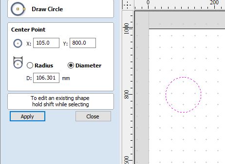
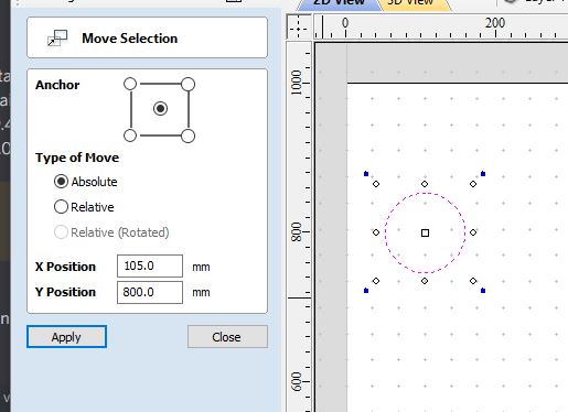
In this first screen capture…it’s placing the circle. The second is the MOVE menu for that same sketched circle create-draw a circle move place the circle
for ref…the ‘anchor’ lets you pick the center of an object or a group of objects and use the center or any corner as the reference point for the XY position in the drawing
Having some way to specify a specific xy coordinate to placing a sketched or group of sketched items would DRASTICALLY accelerate the tedium of trying to retro edit files and mate parts
I’m not sure if I understand the problem correctly, but why can’t you do this using constraints? You can position sketch elements relative to each other with dimensional constraints.
Hi @Istvan,
I think it is about the fact, that neither the origin, nor the axes are objects you can relate to for a dimension.
It would be great if that would be implemented in a future release - meanwhile I propose following workaround:
Start drawing a line at the origin
Click on the endpoint of the line that corresponds with the origin and lock it
Relate your dimensions to that point
You might as well turn that line to a construction-line
It may be even more practical ti draw 2 Construction-lines in both X and Y starting at the origin and lock the points at the origin - then these lines can be used directly fir dimensioning distances in X and Y without fiddeling around with the orientation of dimensions between two points horizontally or vertically.
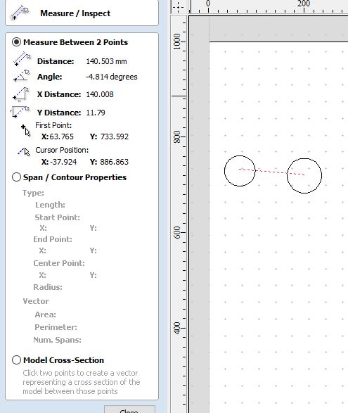
Perhaps an alternative or first step might be simply enhancing your measuring tool
As an example (from that same program… having simply place two circles in the drawing… then selecting the measuring tool and clicking on the two centers of the circles produces this info… measuring tool
For reference…this app is Vetric’s VCarve Pro. It’s a CAD/CAM app geared towards tool path generation for CNC machining. 2D drawing, then expand the drawing into toolpaths (extrusion in your case…but here we apply tools to the 2D drawn items)
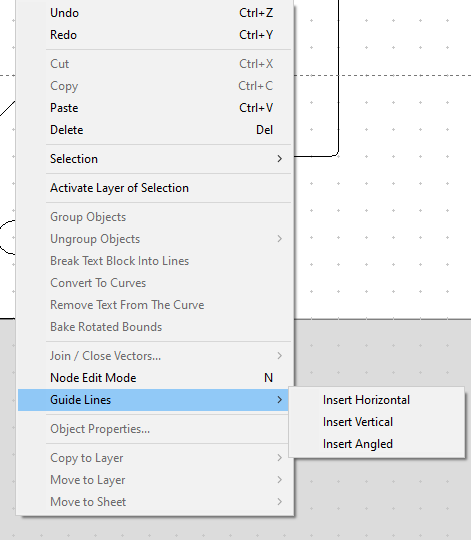
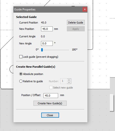
ok…got an alternative to this coordinate system, reference position issue.
Again this same CNC app, has an environment function that is NOT captured in the data file of the drawing, call guide lines. It lets you place reference lines in the drawing, as well as contextually move and place them as needed, bot hort, vert and angled
the first screen cap here is the right click screen context menu…you screen context menu
once the dotted line is placed on the drawing you can move it as needed/desired by clicking the line adjust guideline position
These guide lines do not interfere with any part of the drawing modes (EG: won’t cut a circle in half when selecting etc) they are screen functions only and not part of the drawing. Seems this would be a quicker reference system especially when drawing multiple items across a screen that may need a common reference point.
just food for thought

