I took the same exported STL from Shapr3D, ran it through OpenSCAD and re-exported as an STL and it printed at 25.4mm!
So it would seem that one of the updates from Shapr3D has broken something. I was previously able to print the other half to the original model at the 25.4mm inside diameter just fine but now it will not will do so. I have been beating my head against the wall for literally months, thinking I was doing something wrong only to really understand that Shapr3D is not allowing me to be accurate in my prints.
I’ll gladly work with you to help sort this but it is truly frustrating when I have a client who’s been super patient, waiting for this to be done.
May I ask you, please, to let me know if you see any difference in the bounding dimension of the ring in the slicer software?
In the meantime, I just measured the circle STL you sent in Rhino by placing a three-point circle on the vertices of the mesh. The inner circle is 25.4 mm, the outer is 29.4 in diameter.
I see that you find Shapr3D the weakest link in the CAD-mesh-print workflow, but it is unlikely to distort only the inner diameters during a CAD-mesh conversion export where the tesselation is done according to a uniform tolerance by an algorithm.
I also checked the models in Shapr3D by painting the CAD model to red and leaving the mesh gray. They have the same effect of overlapping faces as the cylinder from my previous post:
You are trying to find differences but you aren’t using the same tools as I am. So it’s like. your tools are simply validating themselves but not the final output.
May I suggest a file comparison tool?
Take my Shapr File, export it as an STL. I’ll upload the STL file generated by OpenSCAD and then you can compare the differences. That way we are both doing the same thing. Sound fair enough?
Sure, let’s give comparing the STLs a try, please upload it.
If the STL that you uploaded yesterday was exported from Shapr3D, it is enough to upload the one from OpenSCAD. I already have the one from Shapr3D, I made the measurements on that exact file.
Comparing the g-code on the other hand is not the right tool to validate the files. It is an output generated according to the settings of the slicer. If there is a setting that shrinks the sliced model, for example, there is already a difference in the g-code leading to the conclusion of inaccurate file export from an independent software. Please stick with the files for the measurements.
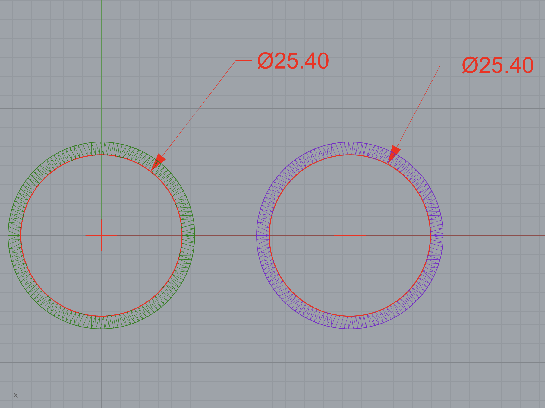
The green is the SCAD, purple is the Shapr3D version. Measured with the same method as yesterday, I placed a three-point circle onto the inner vertices along the upper edge.
I checked the models in MeshLab also, they have the same number of faces (1040) and vertices (520).
I did have that thought as well. Just not had the time yet to test it out.
The biggest concern is that you are only testing with software and not output from said software. I’ll get to testing this idea out as soon as possible.
I tested the files in a software that is independent of Shapr3D and OpensCAD just to measure the geometry. Comparing the G-Code which is a processed output, possibly deformed by the slicing settings may lead to false results. It is an output of the slicer, a toolpath.
What would be your choice to compare the two STLs without further conversion and transformation?
There is a thought from you that it’s not Shapr3D. When I do not use Shapr3D but use the same slicer(in this car, PrusaSlicer), everything is dimensionally accurate after output. When you use another piece of software, that does not represent the issue I am experiencing. It’s the STL output, generated from the Shaper3D STL file where the problem lies. Whether it’s PrusaSlicer interpreting some specific output differently than what Shaper3D intends, and this is my suspicion, or it’s something else, I don’t know. This is getting into a level of detail that I’m trying to understand how we can narrow this down.
When I use an STL file, created by ‘some other program’, its accurate. So, it’s a bit hard for me not to point the finger at Shapr3D as the reason for this, with my setup.
I know that PrusaSlicer internal Shape Gallery prints fine. I know the 20cm cube STL downloaded from Thingiverse prints fine. It seems that some code being output is telling my slicer to do something different than what other programs are. It’s subtle, it has to do with scaling because otherwise the resultant print is exactly what I want with the exception of it being just ever-so-slightly scaled down.
I’m not sure if this will help, but I running Shapr3d on an 11" iPad Pro, running iOS 15.6.1. The app version 5.253.0.4344 #2692914f.
PrusaSlicer 2.5.0
MacBookPro, mid-2012, MacOS 10.15.7.
It may be possible that the Mac version of applications are interpreting something differently but this is a bit of a stretch as one would think that is independent of the software output.
I ran a program called Meld. It allows the comparison of two different files. I did see differences in output from Shaper’s STL vs another program. I noted quote a few differences, some where very minor (like xy location off my 0.01 or 0.02) which is not enough to cause a 0.5mm difference. In other areas, there were some notable changes. I’ve attached a screenshot below. On the right, each blue-line presents a difference in output from one program to another. While it may be reasonable to expect to see some, I’m not sure if the number of differences are reasonable in this particular case. Hence why we are discussing this
Hi Don,
I know you spoke about using .3mf-format 24 days ago.
I am courius: Did you try the same with .3mf-files and was the issue the same?
And it does not even stop there: If you use Prusa Slicer you can import STEP-files directly (from version 2.5 on).
I understand that you would like to know where the differences come from, but meanwhile you could use a non-mesh-file-format and happily print things.
I guess the differences are caused by different degrees of approximation (both files should be exported with the same values for angle- and deviation-tolerance) - but I neither can proof that, nor do I have the time to look into this topic this evening.
If I where you I would simply use a “better” file-format for the application.
Stay safe.
Cheers Matt
First I’d like to thank you for all the effort you put into this topic, I’m really interested in the result we’ll end up in.
May I ask you, please, to print two models made with Shapr3D and any other software in the same printing project?
Comparing the G-Codes in my opinion can easily lead to inaccurate consequences as g-codes are generated from the exported STL files based on the slicing settings and the unique parameters of the printer.