Bear with me. I’m not an engineer nor CAD modeler and will try to describe this as best I can. I am designing a hollow human head model to 3d print in which I will place hexagonal plugs made of electrically conductive filament (see clip of hexagon moving out of the head model). The inserts will match the 10-20 system for EEG electrode placement and will be used as a teaching model for my students. The electronics will be inside the head with a signal generator to produce a 10uV 10hz sine wave. There’s absolutely not danger of electrical shock. I am using a hexagonal model for the plug and socket with which I used the Shell command to make the walls 0.1mm thick and used this to splice the hexagon plug from the head using the Subtract command (see clip with the hexagonal hollow body that I insert into the head to produce the socket and plug (here labeled T3). This gave me a head body with a hexagon plug that exactly matches the contours of the site. I will repeat this process for 19 sites. My test print shows that the 0.1 tolerance works well as the plug will move in and out of the socket with just a little stiffness and enough tightness to help minimize the build up of conductive gel used when placing the EEG cap on the model (see clip of the slicer with me moving the plug in and out of the socket). For the test print I removed a circular plug from the head with the socket and plug. Now I need to design a way to keep the plug in the socket with a snap fit that would allow for the removal of the plug with a little effort for cleaning and maintenance of the wiring. Here’s where I am stuck. I’m thinking of adding a little notch about 2mm inside the surface to produce a groove around the socket for a protrusion on the plug to snap in to (see the clip of my sketch of the notch. Image this would wrap around the hexagon hollow body I use to subtract the plug from the head and create the socket using the Subtract command. I’m thinking I will start with keeping the walls of the hexagonal model at 0.1mm and starting with a notch with approximately 0.2mm offset and increasing with prints until I get a good snap fit. I can’t figure out how to design the offset going around the side of the hexagonal model and keep the walls at 0.1mm.
hexagon with socket and plug.zip (162.7 KB)
Are you just trying to add tolerances between the head and the hex part you made?
I’ve established the tolerance. I’m trying to add the “notch” around the hexagonal body I move into the head to create the plug and the socket when I subtract it. I don’t really have the vocabulary to describe it. It’s a half circle protruding from the 6 sides of the body so that it, and the body walls, are 0.1mm thick.
Like snap fit.
I would take a look an already made snap fit and print on out and see how the mechanism works and see how much tolerance is needed and such.
If it’s too small scale it, make test pieces get that working before applying it to your final model.
Also if it just need to hold, instead of notches you can consider more simple rounded version on the wall of your hex.
Or personally I like magnets to hold things that needs constant unmounting.
I’m concerned that magnets would interfere with the signals which are uV (a millionth of a volt).
This is one of my failed attempts:
I tried to extrude a half circle and use the Shell command to make the walls 0.1mm thick, cut it by 60 degrees on both ends to have pieces 20mm long, and align at each end to make a hexagonal shape, but alas the ends would not align. I was hoping to create the indentation that would exist on both the socket and plug, but no dice.
20mm hexagon with .2mm notch at 2mm.shapr (130.4 KB)
You can use the edges to sweep.
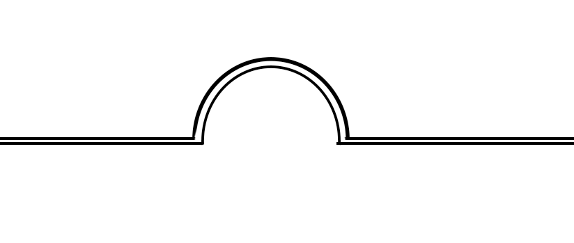
Sorry, I can’t tell what you’re trying to illustrate. What I need is something like this around the edges of the hexagon. Imagine this a diagram of the outside walls, if that helps, and the half circle is the “notch” that–when this is subtracted–will leave a negative indentation in the sides of the socket and protrusions along the outsides of the plug.
Use perpendicular to edge construction plane so you can draw the indent.
The sketch can be swept using the hexagon edges.
First sweep is inner part and the second is the other part.
I just did one side but you can continue the sweep by selecting all around the edge.
All I have to do now is test it out!
Thanks so much to both of you. Getting to watch masters do some designing is mind-blowing at first, and then amazing once I figure out what it is that I’m seeing. For example, Alex, I couldn’t figure out that last step until I saw the Shell command button change color and then I knew you were using the Shell command, and I was then able to replicate it–impressive!
Kyun, I had a challenge creating that first sketch with the two parallel shapes. I expect you had some straight forward way of doing it. Otherwise, it was quite ingenious the way to constructed the model.
Gratefully,
Mark
Lot of times I’m very impressed with the problem people bring up in the forum! It will be most helpful when I face the same problem!
Wow. I didn’t even understand the brief until Xdrakosha, showed this video.
Absolutely, stunning solution?
I presume the point of this groove is so that the plug remains snapped into place?
This community is amazing. The amount of time people give up, to help others, is quite frankly, humbling.