Spline segments to closed curve? HowTo?

Hallo,
I’m struggling a lot with my imported curves.
Oject: importing topographic lines (closed curves) to 3D model them and 3D print.
Import is a DWG file from Corel Draw with 2 closed curves:

Topo_600R_closed_smooth_nodes_test.zip (17.1 KB)

Corel Draw has 3 types of nodes for curves: cusp, smooth, and symmetrical
The exported nodes are all SMOOTH
The curves are Bézier curves and shapr3D Help page says that Bézier is supported.


The exported curves are the selected blue one and the red one.

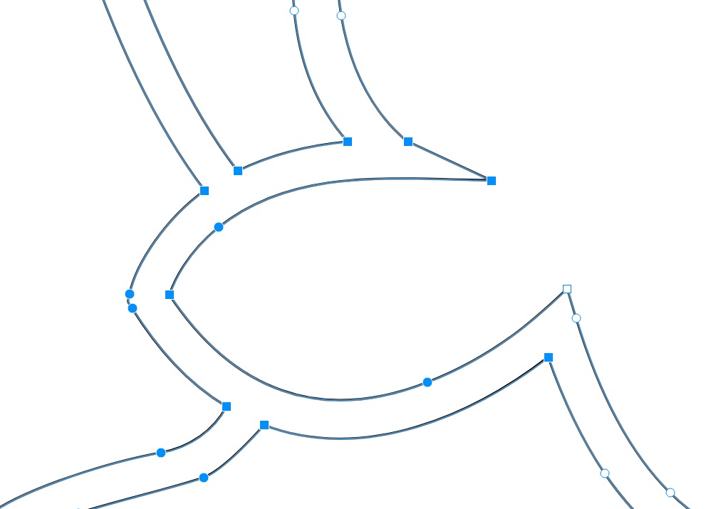
In shapr3D I get these curves :


I notice that all the nodes are blue circles but not filled dots, they are named ENDPOINTS.
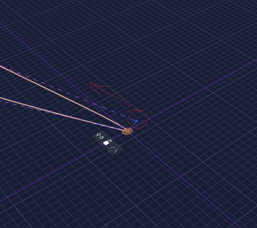
Selecting 1 node brings this pop-box:

What do these icons mean?

  • connected ?
  • unlocked ?
  • what does the arc mean?

Selecting the blue curve , only selects a segment of the curve.


How could I get these segments to be only 1 closed curve (or do you call it spline)
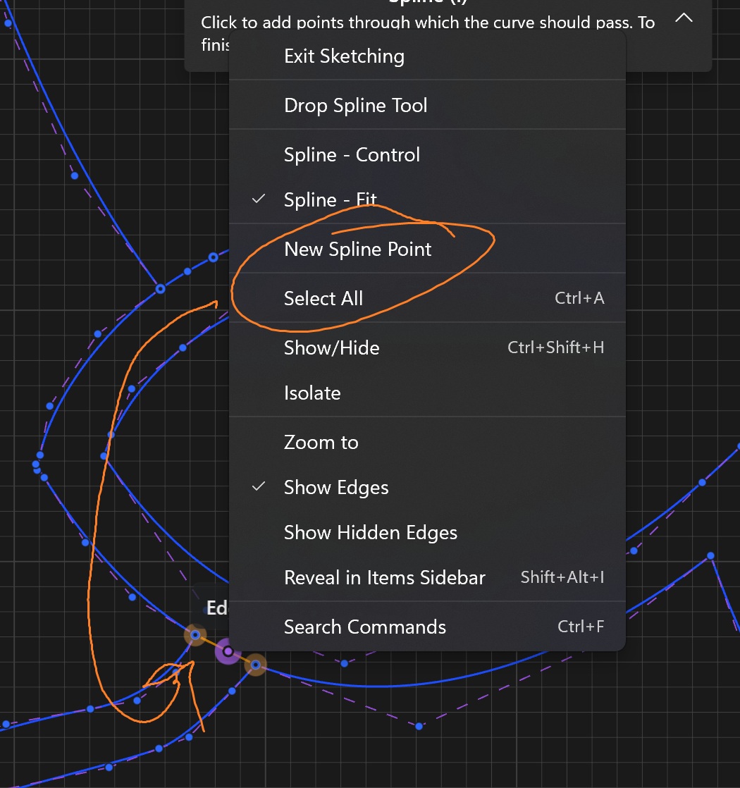
I noticed , when clicking the little arc icon of a node, this changes its color to filled dot, BUT the overall curve changes, and the node is now called CONTROPOINT.
Once all the nodes are clicked and changed to full blue dot, it is possible to select the whole curve by 1 click on the blue line, as if it now is a single segment.

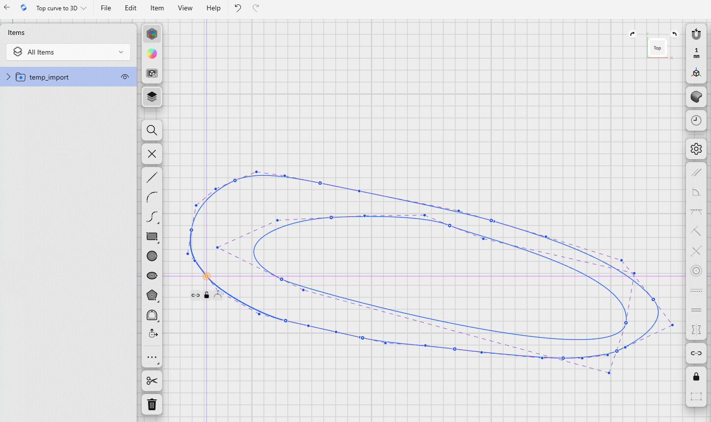
Doing Offsets is now possible, BUT after some mm the drag arrow gets red .
If I end the offset just before the red arrow appears, I have a new offset.
Looking at the nodes of the new offset I see that there are new nodes which appear as circles, not filled dots. Selecting such a node brings the again the 3 little icons, after clicking on the arc, the node gets filled blue and I may do a next offset edge.

Same difficulty to do the loft, but more complex due to the control points.

Could somebody guide me to get these topographic curves lofted?

Thank you so much for your help.

The arc changes the the point from an end point of a line segment to a control point connecting them together I think. If you had 2 line segments connected it combines(?) the two segments? That’s why it changes the line I think.

For some reason your segments aren’t connected if they do not create closed shapes. I export DFX from Corel and do not have that problem.

If I wanted to make a solid from a topo-like map, I would use offset planes to “project” the elevation lines to and then loft them.

Can you use the bucket fill in the shapes in Corel? I customize fonts by converting them to lines, edit them and import to Shapr as DFX with pretty good success.

It’s late here. I can look at your drawing tomorrow.

Thank you for finding some interest in my problem.

I narrowed it down a little bit an I am now quite sure that it is a Corel export problem, maybe due to the Bézier curves.
My Corel is the 2018 version.
Exporting as SVG and then saving the SVG to DXF with Inkscape gave me some options while saving to DXF.
I was now able to move each topo contour on the Z axes and do a loft from one contour to the other, but the automatically generated guide curves are badly positioned and often can’t be moved.
I do nit understand the reason why they can not be moved. In the tutorial videos it is so easy to relocate them on the contour.
With the Inkscape DXF files I get mostly only one white dot per contour when doing the loft.
It is really difficult.

My prior version was Corel X6. It has always worked fine exporting as DXF. Never tried DWG.

I notice that too. Bug?

If you offset (outward) the offset again you can go twice as far before it turns red. Strange.

The ARC icon toggles “cusp” function I believe.

Lion.shapr (28.7 KB)
In this sketch I have the same problem, on the inner loop of the tong I can do a 0.3mm offset edge, but not more.
Can somebody explain this?
THe outline shape of the lion can not be offset at all. Why?
I checked each Endpoint for its connection, I UNCONNTECTED each Endpoint, moved it away, regrabbed it and brought it back onto the other Endpoint. A this moment I get a new Connection.
But I’m still not able to do an OFFSET.

I need to understand how these Endpoints and Controlpoints work with their Constraints.
Please give me some tips and tricks to understand them.
I looked at so many tutorials and they always look straight forward, but mine not.

I moved that control point and was able to do an inner offset as much as I wanted.

Noticing some things here. Maybe it is as you intended but they look worth examining. I made a rectangle around the design and tried to offset it. It did not work. I will play with it some more. Can you attach the Corel file?

Corel Draw has a “Reduce Nodes” function. Have you tried that? Some of the nodes look a bit wonky. (Notice the 2 close together, one could go away). I always reduce nodes before exporting to Shapr especially on “captured” images converted to vector. I also use node smoothing in some cases too. Takes some preprocessing to go from Corel to Shapr but it is usually worth it.

Shapr free hand drawing and node editing tools are too rudimentary for my liking. But then I’ve used Corel for ~30 years… I consider it the best for node editing. I used to do a lot of tech sketches with it. Instruction sheets etc.

I’d would love to see it work for you :sweat_smile:

Also: I suspect the Tongue area is key to the offset problem but that is just a guess. The offset might be better done in Corel first. If you send the file I could better help. I don’t charge :blush:

Yes you are right for doing the offset in Corel, but it is a project I want to do with my students and they do not have Corel on their iPads, but shapr3D .

To the marked Endpoints in your screenshot.
The unconnected blue to orange lines should be like that. I opened these connections to simplify the outline of the lion and reduce problems.
The very near double points came while unconnecting - reconnecting points. They were wird Endpoints hidden under Controlpoints. I dicovered them while moving and replacing each endpoint.

Here us my starting point in Corel draw:
Lion 2025-12-07 18_29_07.zip (36.6 KB)
As I may not upload .cdr files, I hope this zip file works, I made it with my iPhone.

l

I also suspect these control points to be part of the problem. They are totally different then the Bézierr curves in Core

for the 3 icons my understanding is now that:

  • the chain icon: present = endpoints are connected, icon signification → break existing connection
  • opened lock: =point is locked, signification → click to unlock the locked point.
  • arc : I’m not sure, point is not a smooth point, signification → make it a smooth point ???

My understanding for the points is :

  • small blue point: Endpoint OR Controlpoint
  • big blue with white center : Connected Endpoints
  • green points and lines : locked ??? I’m not sure!

I absolutely need a tutorial for all these points, just explaining them and their relationship.

I think this tutorial does exist, but I can’t find it , or do not really know what to search for.

Changes end point to control point and vice verse.

I recommend reducing nodes by selecting areas with the node editor. It rarely affects curves but reduces the information to be exported. I changed the lines to “hairline” and removed the color.

After reducing nodes and exporting as DFX I was able to easily offset edges.

each time I have the red arrow, the offset does not work.
Could you please share your CDR and DFX files so I could compare them to mine?

Now I can section off in the sketch view with line segments. I have always used DFX since my start with Corel. Sending off designs for test fixtures to be cut. Never used DWG.

I hope I have helped and not further frustrated your efforts. :grin:

Let me know if it works. I closed the Corel file without saving it so I redid it. :hand_with_index_finger_and_thumb_crossed:

Note: When you export a DFX, that format adds it’s own nodes after your reducing them in the native Corel file.

LionEdited.zip (61.6 KB)

It’s a stormy day here. I might lose power. If I do not reply…

Where do find the menu in your shapr3d screenshot ?