I’d like the materials to adhere almost water-tight and I don’t mind over-extrusion, so I think I’ll skip the second step.
If there’s some shape you know about that you’d recommend for maximum adhesion given my description, I’d appreciate it! I went with a very simple shape to start with
@TigerMike always has the best answers! If one of your materials is TPU (flex) you might be able to use Mike’s tapered lap joint with a negative draft angle. This would give a joint that you’d have to force the pseudo dove tail together, so it might take a couple tries to figure out the best angle.
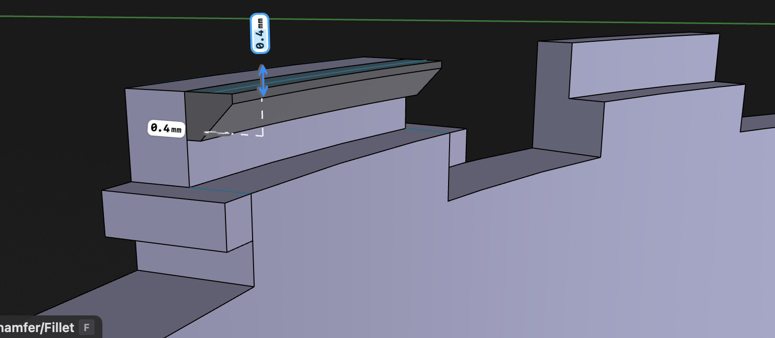
I’ve got a shape I think could work (maybe there’s no advantage to having so many repetitions of the interlock? idk) and I’m trying to make a final touch by moving the “top edge” (hopefully clearer in screenshots) out for a tapered lap joint effect. However, when I do so, the edge moves away at an angle.
If there were some way to “centre” the move function to the centre of the tube/ circle, I think this could work easily as I could then just subtracting the new lap joint design from the other part it will interlock with.
Perhaps something like this could maximise adhesion and minimise breakage? If I could centre the move function and somehow automatically replicate the “T” lock addition across “stubs” around the perimeter of the tube.
(I’m fairly new to all this so apologies for my vocabulary.)
That design is way too complicated in my mind, but who am I to say.
You want it to be water tight but all those notches and laps make it prone to leakage in my opinion. I’m a proponent of ‘Less is More’. The simpler the design the better.
Do you plan to 3D print with a resin printer or FDM printer?
I figured the whole lock design is only 2mm thick, so it hopefully should not involve printing too many layers. I’m using a 0.8mm nozzle, so at 0.4mm layer height it should only be 5 layers to cover the whole interlocking mechanism, and therefore hopefully only a few material changes. But yeah I’ll probably wind up simplifying.
I worried that a tapered approach might not translate well in practice because of the small size of the mechanism and the large nozzle size, but I may easily be wrong.


