Hi
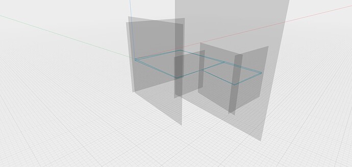
I’m attempting to create a environment of my land plot. I’ve marked measurement points and start from one point, then work my way around point by point. I create a plane vertically on each side of the plot, then draw a point from one end to the other, switch planes, and connect the purple points. Initially, I attempted to use a Construction Line as a baseline and a sketch line for height and passage between reference points. However, this didn’t work. When I solely used a sketch line, I managed to create the vertical blue surface on each side of the plot, but I’m missing the horizontal plane from the top view that considers the varying level differences. In short, the entire plot should resemble an irregular-shaped cube with a top featuring different angles and heights and a bottom that’s completely flat. I’m fairly certain this can be achieved, but I’m struggling.
Any tips?
If I understand you correctly you’re trying to recreate plot surface?
Then I think you can use move/rotate tool on the edges to diform needed parts.
Or you can draw surface curvature from two sides then extrude and intersect them.
Include my Shapr file. I can’t extrude in a vertical view.
Sharp3D 4.shapr (9.8 KB)
Ok, I think I see the solution. Just give me some time to implement it.
1 Like
So… Because you’ve messed a little bit with sketches I decide to start over.
I made a projection from top view of your plot.
Added all needed planes from the scratch
Redraw all sketches from all sides but add 0,5 meter underground just for convenience and because there is one 0 height point on the map and that wouldn’t give to go further.
Constrains everything nicely with all dimensions
Made a loft using two sides and another two as a guides
Then lofted another part using same approach
Then just union two parts and that’s all
Here is the resulted project file
Sharp3D 4 (updated).shapr (57.2 KB)
If you don’t like additional 0.5m underground you can make face offset from bottom of resulted body.
Fantastic job and a big thank you! I’ll download and take a look at this a little later today. I hope I can now manage to add curves to it to achieve a better smoothness and realism of the sketch.
Unfortunate turn of events. I downloaded your file and updated my Shapr3D to the latest version, only to find out that our versions and your document aren’t compatible. If you’re going to update your Shapr3D, please feel free to send the file over once again. Thank you.
Mine is the same version as yours, however it is the non-parametric version and therefore incompatible.
Yeah, I saw that and that’s quite strange. I thought non-parametric should be lower.
So we have a file that I can’t open until I accept a beta version?
Seems so  Sorry but I don’t have other versions. I can’t even install old version. All new users automatically get parametric one.
@danielsthlm and I have the non-parametric version but mine is a beta.
I understand that all new users still get the non version for now until the full blown parametric version is officially released sometime in April.
I suspect that will be a problem that’s why I made several screenshots with descriptions.
Okay, I’m trying to work my way through this with your guide. I’ll keep you updated.
Make sure you lock everything and keep bottom line horizontal always.
How do you align a construction plane to a line? When I do this, it ends up at a 45-degree angle from the line instead of perpendicular to it. From that, I rotate it an additional 45 degrees to 90 degrees, but that seems wrong.


