Drawing Arc with set angles to a circle

I’m not sure what I’m doing wrong or if there is a better way to do this.

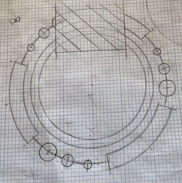
I’m creating a rosette for a guitar. Hopefully the image loaded of my design on paper.

Rather than a solid ring around the sound hole, I’m using a segmented ring.

The segments are 60 degrees each, meaning there will be three segments and three blank spaces. Also, the segments are offset so as not to land on any of the 90 degree angles.

I started by drawing the soundhole circle as a reference. Then the circle that will bisect the segments.

Here’s where the problem starts.

I’ve tried drawing arcs, which I can size correctly and set to the to 60 degrees. I can’t figure out how to have the arcs concentric to each other AND resize the second one to follow the larger circle (I figured I would connect the ends once the arcs were correct. Then I can’t figure out how to locate them in the appropriate spots on the circle.

The other way I tried was to create everything as circles. Then lay out lines at the correct angles. Then erase the “extra” parts of the circles. I create two lines at the circle origin and get the approximate angle. The problem I keep having is that when I adjust the angle, it changes the line on the x axis rather than the other line, meaning I want a line that is 20 degrees off the x axis, but it moves the line on the x axis towards the other line.

I understand I may be going at this completely wrong either way, so any ideas would help.

I tried uploading a photo of a drawing I did before. Not sure if it worked.

Thanks for the help in advance.

Something like this?


Yes.
Also, how do I space the small cicles on the arc so they are equidistan edge to edge (not center to center.)

Here, I made a video: Arcs/Circles - YouTube

As for the edge to edge part, I assumed you meant absolute/ straight distance.

If you want the distance between the circles to be along the arc (i.e. arc length), you need to calculate the angle with the arc length you want from the formula L = 2πr * (θ/360 deg)

For example: for arc length 0.75 mm and diameter 20 mm, θ = 4.2718 deg

Just put the angle between the lines like this:

1 Like

That’s a good video SM1, will be helpful to many people.

1 Like

Thanks for the video. It was very helpful! So interesting to see another approach to this drawing.

Wahoo! I did it. It took a few rewinds on the video to catch all the steps. Mostly noticing where points were locked or the rotation point moved. Super excited to get it done and learned a lot! I’ve been trying to get up to speed on Shapr3d prior to purchasing a shaper origin cnc for use in lutherie. This is my rosette design. I’ve done it before, all drawn by hand, but changed the size this time so figured it was a good opportunity to redraw it in shapr3d.

Thanks again for help.

IMG_0107

2 Likes

My pleasure :slight_smile:
Also, this should be much easier to do when they add construction lines next update or so

Arc from centre point would be useful too. At the moment to control something so simple is incredibly tedious. It is made worse because like the line too the arc tool is sticky, which adds an additional unwanted step.

That actually sounds kind of cool. You start by drawing a construction line that defines the radius, and then start drawing the arc concentric to the point. A lot like a pencil and a string :slight_smile:

It can use the same mechanic as the spline so you only have to press down to define the radius and start drawing the arc