I am suffering with this problem for a while. As I am not an industrial engineer - designer but a hobby designer I am not sure if this is even correct thinking.
I am trying to creat a “ Helix cut out” in the tube, where the cut walls are “PERPENDICULAR “ to the tube’s centre axis. So if I would drill a hole 90 degree to the axis and would move up a notch -turn the pipe few degree and keep drilling that way I should always have a wall perpendicular to the centre. When I design a helix shape to “subtract “ from the tube, the walls are “twisting” According to the helix concave walls.
The “PIN” which needs to be riding in this opening is touching ONLY THE INNER OR OUTHER EDGES of the walls.
I understand the reason for this, but is there a method in the industry - (designing) like as per CNC machining where the cutting bit would be stationary and the tube would move and rotate around the axis? That would make the walls aligned ? Thank you all for the input, if any Ed.
Many thanks. I was trying to do this too. But had problem with aligning the shape if I needed to go 90 degree from start to finish. The opening was tapering on me? But I will try again to see if I am wrong somewhere. Will report soon. Once more thank you and have a great week. Ed
Hi Edward,
Here I made a helix by revolving a square about an axis 180 degrees and giving it some height. Then I subtracted it from a cylinder tube. I don’t think it is “twisty”… The video is a series of undos as I needed to keep the file size down.
Back again.
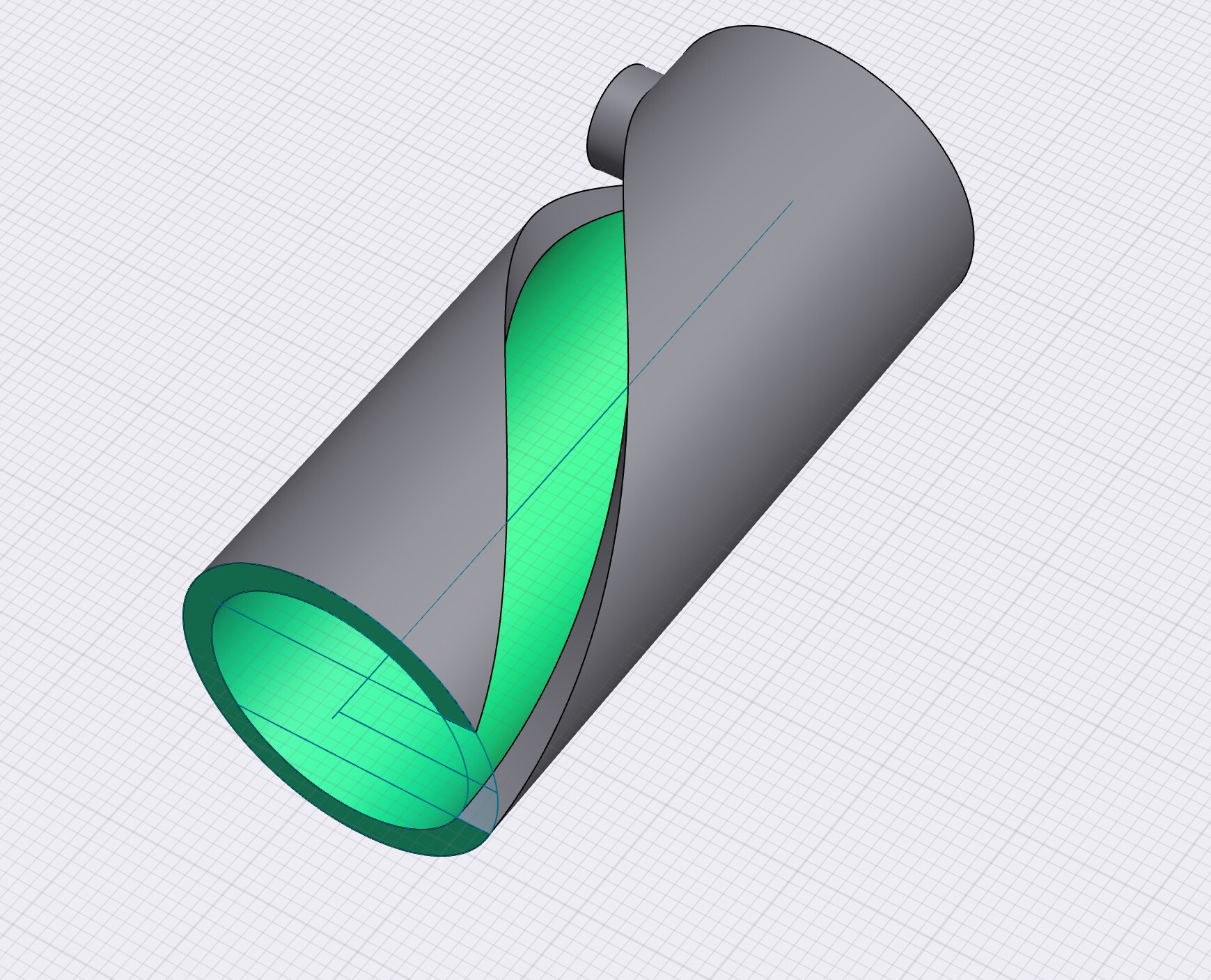
So once more here is the issue I can’t resolve and probably it’s just not possible due to the geometry.
You can see the differences in the shape of the helix body. It does not stay with the same dimensions . Also the top / bottom of the helix is offset to the axis.
It’s a hard project to solve.
But thank you all for you input and support.
Ed.
Here’s a better approximation. Angle the sketch before doing the Revolve. Adjust the height of the helix so that it is normal to the angled sketch (as best you can). Still not perfect.
Or, if the height is a given, adjust the angle of the sketch accordingly.
In the end, maybe the height of the sketch needs to be 8mm+.
I think @TigerMike is right, the sketch needs to be bigger than 8mm, Maybe try this: use Shapr3d to help you figure out the height of the sketch. Draw a line that is the slope of your helix. Make a parallel line 8mm from that. Draw a vertical line with endpoints on each of the parallel lines, and use that measurement as the height of the face you revolve. Here is an example with 55 degree slope showing you would need a square 14 mm (giving a small clearance, you may want more…)