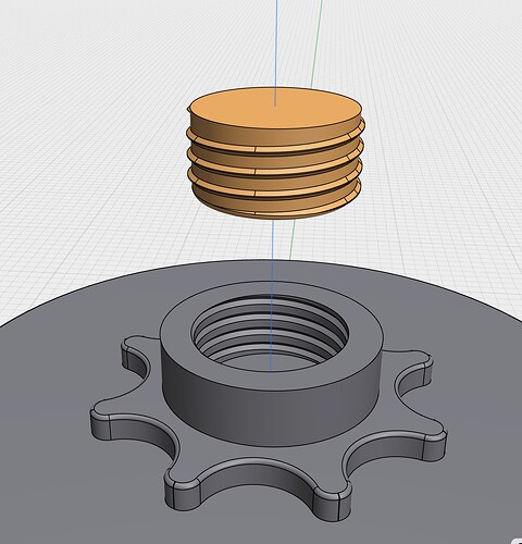
hey all, so what im trying to do is thread a 23mm shaft into this file here. the file is for a display and I want to be able to adjust the display height. the hole in the top of this plate is 23mm, just like the shaft. ive figured out how to make the threads but im having issues with cleaning the top surface of any thread that extends above the body. im having issues with the threading of the body that the shaft should go through. so what im looking for here I kind of a thread that could really cover how to do this so I really learn the process. I think I need to relearn my whole approach top threads as I think im filling my head with garbage ideas. thanks so much for your time and I look forward to working with you guys.
wheel f.step (105.9 KB)
Like this?
That’s exactly what I’m trying to pull off. So how did you get the “female” side of the thread to work on the plate? I’m confused about the whole thing? Can you send me the step file so I can compare it to what I’m doing? I need to figure this out. Thanks a ton
Ok I’m going to get heavily into this today. Yours is just so clean. When I make the shaft threads match the “nut” threads I have to keep track of the rotation amount and the height of the thread correct? That way they match? I’m also 3d printing this so I’ll need my thread angle to be 90 degrees…45 each side of the thread, as my printers overhangs start to degrade over a 45 degree angle. I just watched your videos on my iPhone without my reading glasses so I’m really jazzed to hop on my desktop and really see all your moves. Such a huge help
Yes, of course. I just show you method. You have to calculate everything as you need it.
If you have threaded stud you can substruct it from your nut and that will create required tread. Thas’s what I’ve done on my second video here. If you need another video with this technique just tell me.
Just make numbers in your sketch fits your needs.
Ok, so for the “nut/female” part of the two threads make my shape and rotate it around the inside of the radius. It “cuts” into that radius and creates the thread. I set the thread shape how I need it for my printer to be able to print it. When I go to create the bolt threads the threads extend off of the 23mm shaft size. That thread size should be decreased by a certain amount due to friction correct? What gap size do you suggest?
That’s right.
That’s really depends on your printer. For example mine FDM doing good with 0.1 mm tolerance, so I decrease 0.05mm from both sides. mSLA have better tolerance, I usually set not more then 0.01mm.
Awesome. Thanks so much. I’ll get back to you when I’m done. I have to chase kids around for the day so I’ll hit you up this evening. Thanks so much
why the heck don’t I have the history panel like you do? I dont have the clock icon on mine
I figured it out
I have parametric based version
I found it in the beta version. I’m checking now. It makes the adjustment of the plate thread doable
Ok. Test printing the plate and then I’ll attack the shaft (that’s what she said)
so why the crud dont these want to fit together? what am I missing here?
try this.step (950.0 KB)
You have little to no clearance between the outer body and the inner (plug) body.
What are your slicer settings? Layer height? nozzle size? filament?
I took your plug and scaled down the X & Y to 98%. I removed part of the bottom to give some clearance. FWIW, try re-printing this plug. See if that helps. You may need to redo and add more clearance between the two.
Plug.step (1.1 MB)
I just did the same thing, but I did it to 95%. thanks mucho
cool. ill go over it with a fine toothed comb. thanks


