Bayonet lock

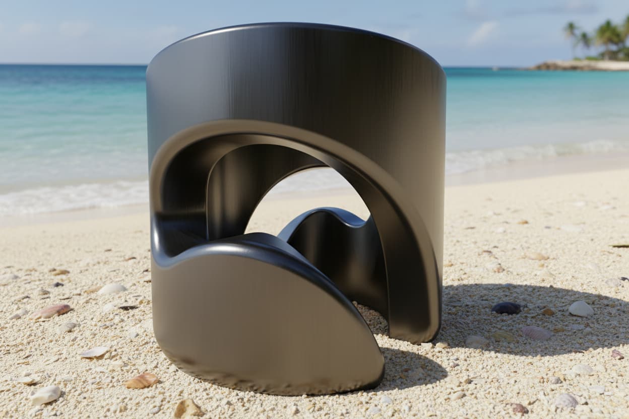
Hey guys. I want to design a bayonet lock, following a clearly defined path that can be easily adjusted to test the best setup with 3D printed prototypes. I have a cylinder as a basis and would like to extrude the material along a defined path, like if a milling head of 4.5 mm diameter would do the job. The path should start vertically for 8mm and then turn horizontally to rise in a 20 degree angle by a height of 4mm. Finally the pocket should have an additional depth of 0.2mm to block the lock (an axial pressure will be applied on the lock).

My attempts up to now resulted in a pretty crooked groove :grinning_face_with_smiling_eyes:

Looking forward to your ideas, thanks!

Best regards,

Patrick

1 Like

This might work for you.

Thank you very much Mike! I thought of this before but maybe my thinking/approach was just to complex - I will try it again.

1 Like

Maybe you still need to integrate springs?

Mit freundlichen Grüssen

Andreas Desiderius Haudenschild

I personally like this Fastener!

1 Like

It’s missing the lobe/ tension catch. Otherwise elegant.

Not sure how I would do that tension catch in Shapr3d.

It’s easy to do in another program!

I can at least import from another program and render to a nice environment!

Awesome :smiley: how did you do that rendering?