I’m a noob, with no CAD experience. I’m a quick study, and have been moving along with my project; an invention idea I am working to prototype.
But I reached a place where I could not figure out what to do.
I need a hex pattern inside of a circle on one of my planes. I made it all out of lines, finished it off, and went to punch it through, which resulted in the opposite of what I wanted. I need the squares inside the lines punched, not the lines, duh. Didn’t occur to me till I did it.
Can someone help me achieve what I am trying to make?
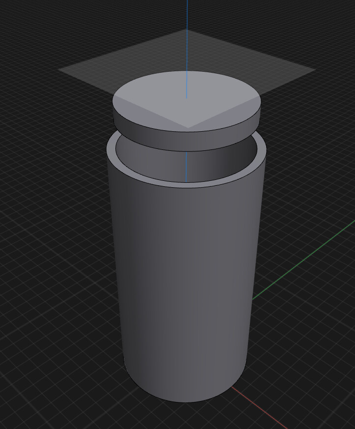
Here is an image of the plane I am dealing with:
I am not sure it’s completely clear based on this screenshot what you’d want to achieve and what happened – all I can see is a circle on the face of a cylinder? You mention hexes but then also squares. Could you maybe record a short video or take more screenshots in which we can see things in 3D?
Thanks for responding! I’m sorry, being new at this, I didn’t figure I would explain myself completely. I guess Hex Grid wasn’t the right choice of words. Crosshatch might be a better term.
I am making a blade of sorts. The product will be pushed through the blades and into the cylinder.
On my initial screenshot, there are 7 lines going in each direction inside the circle, those will be my blades, about a mm in thickness.
I was doing this on a separate plane and then going to push it through the disc above the main cylinder body, which will be merged with the main body in the end.
When I initially mocked it up, I made the lines and pushed it through, but that only made slices in the disk. I was like, duh, after I did it lol. I basically need a mirror of that. Instead of the lines pushing through, I need the squares to punch holes, leaving 1mm “blades”.
I hope this makes more sense. I apologize if I’m not describing it properly.
No worries, your explanation was great, I get it now!
I think what you should try is the pattern tool and then boolean operations, either intersect or subtract. The main idea is to set the pattern spacing to {size of your hatch item} + {desired width of the “blade”}.
Here’s a rough example of how I’d approach this:
In the live version of the app you’d need to recreate the steps if you wanted to adjust the parameters of the hatching. If you’d like to be able to do check different variations dynamically, you might want to give the parametric beta version a go, where you can edit the sketches, even the sketch pattern parameters and the subsequent steps (in this case the extrude and booleans) will adjust to that automatically.