I am using Loft to create a model of a vintage car bonnet. I am finding it extremally confusing to work out what causes bulges and dips without using trial-and-error. Is there a detailed explanation/tutorial on the advanced use of Loft to help me understand the root cause and adjust?
I also keep getting this error message “All profiles should be positioned in a way that the lofted body won’t self intersect” What does this actually mean so that I can successfully de-bug the issue?
A hose folded over tightly would be an example of self intersecting.
Guided Loft is the way to go. Make sure the guide lines touch or connect to the loft planes (circled in red).
Hi,
Thanks TigerMike.
I can see how this works when the edge of the loft is in a single plane. However I have a profile along the bonnet side view edge (actually it is a bonnet half). So I have profile 1 in the image below as the top view edge but also profile 2 as the side view edge. Any suggestions how I can make the guided Loft work in this scenario?
Sorry to say that I do not follow at all what you are trying to do with your profiles 1 & 2.
(Maybe it’s a right-hemisphere thing  )
)
The use of guided loft doesn’t have to be in a single plane however it is a bit more work creating guide lines outside the initial single plane in 3D space.
Not sure if this applies at all but you can do a secondary operation as shown below. Again, this may not be what you want to do but it may offer another approach.
Thank again Mike.
I see what you have done in the clip but it will not work for me - I make model cars and am trying to replicate an existing model piece so I can improve on the original and then 3D print - so the dimensions are important.
I think I need to do as you say and create the guide in 3d space to do this if I am to use guided loft. Otherwise I think I am stuck with lofting between cross section profiles.
Any guidance on how I generate a 3D guide as I cannot see how I would do this in Shapr ?
( I have just tried using a projected edge in 3D space but does not seem to work)
Can you upload a pic of one of your existing model piece where dimensions are important? I’d like to see what it looks like and perhaps offer a different approach.
Here’s an example of using guided loft in more than one plane. The features are exaggerated so the result is easier to see.
Mike,
Many thanks for your interest.
Screenshot below is the best I have been able to achieve so far - but not perfect.
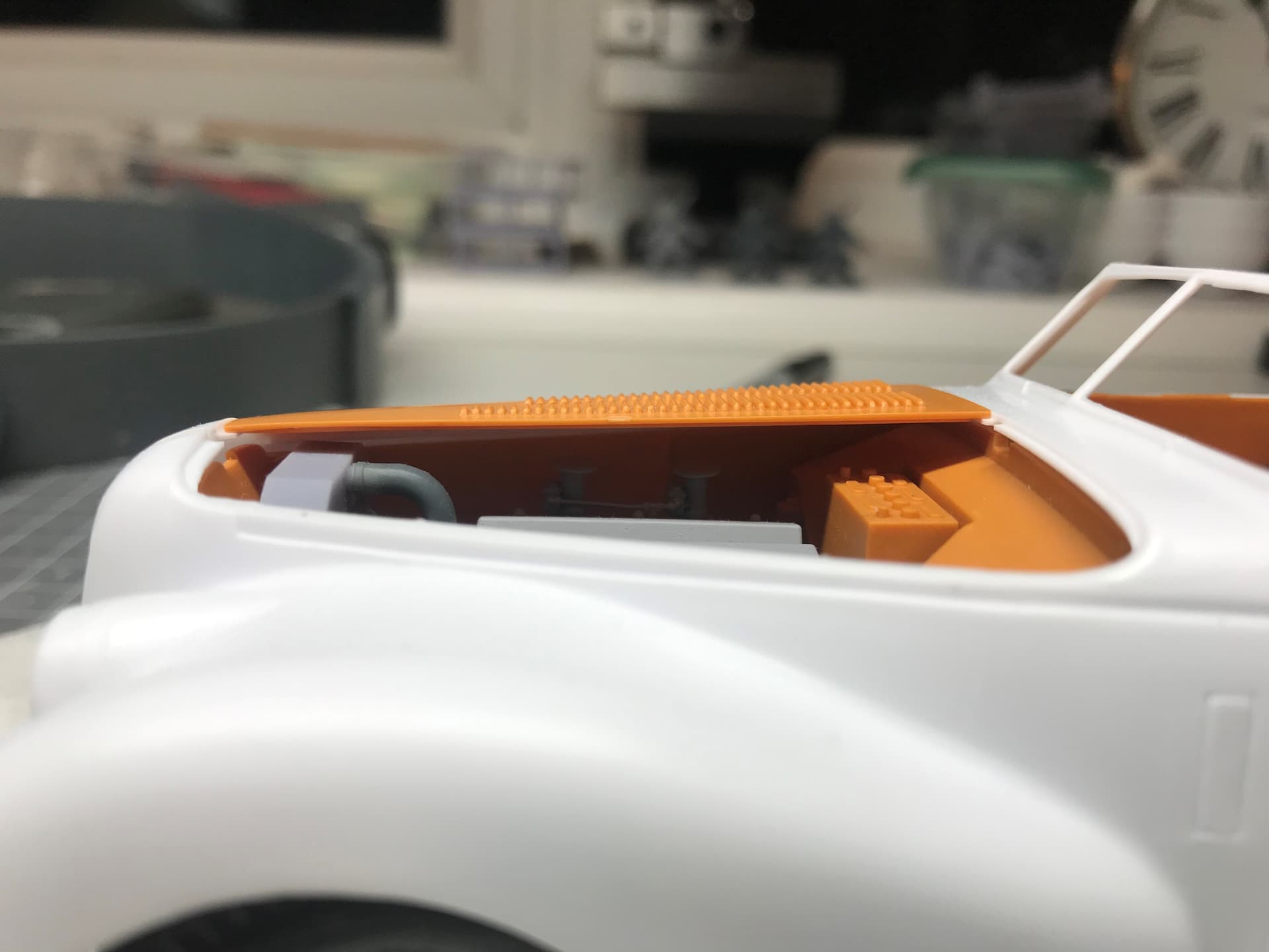
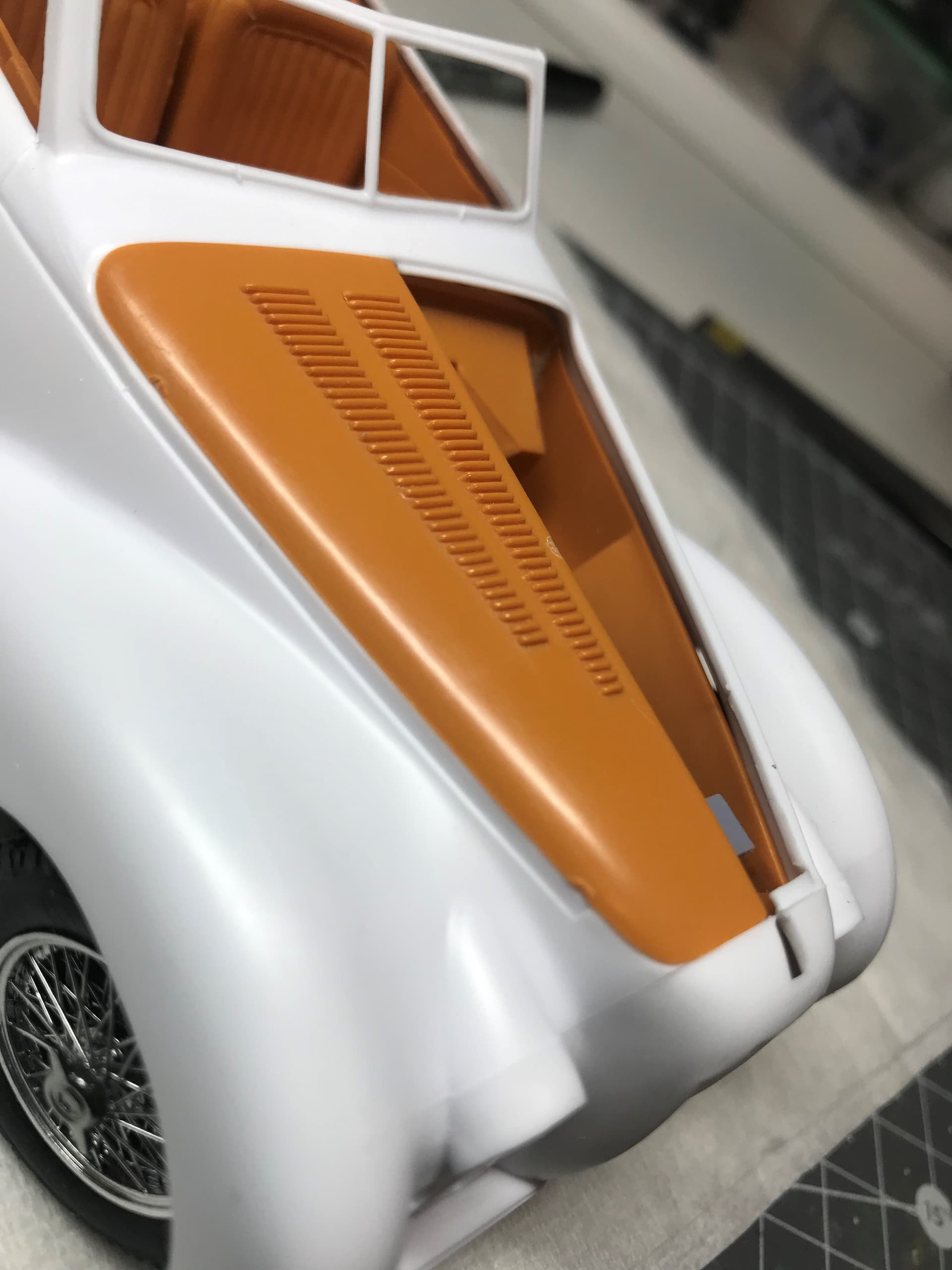
Pictures below are of the bonnet I am trying to emulate. Ignore the louvers - these are the reason I am wanting to 3D print my own as you can see the kits depiction is pretty poor. I have already mastered how to do these as you can see.
It is now just a case of getting the basic shape correct.
For clarity - the blue one is my attempt - the louvers are good but the general shape is wrong. The orange one is the one I am trying to accurately model.
Thanks for clarifying and for the pics. Nice model. I too like model kits. I think trying to do a complex loft is…shall we say, too complex.
I would consider my 2nd approach with a double subtract after the initial loft and shell.
Are your 3D printing with a resin printer?
Hi Mike,
I took your advice and I think I have cracked it. I needed to produce a Loft Guide for the front edge that was at an angle to the x plane which was a little more involved. I will now need to 3D print a prototype and adjust from there but the process should be straightforward now I have the workflow (thanks to you). see below.
I am using resin printers and have already done the engine - Shapr pic and pictures of the parts and finished product below.
Many, many thanks for your help. What are you working on at the moment?
Steve that looks great, what type of 3D printer are you using to make your parts.
Thank you
Hi,
I am using a Phrozen Sonic Mini 8K with Phrozen’s Aqua-Gray 8K resin for most of the detailed work. I also have a Prusa SL1S which is great for prototyping as it is around 3 to 4 times faster - but the trade-off is in the resolution/level of detail.
Steve,
Glad it worked for you and am happy to have helped you out. When it comes to sketches and modeling, I’m a proponent of ‘less is more’. That’s a really nice model- both the physical and the engine CAD model.
I have three FDM printers that gets lots of use. I recently bought an Anicubic resin printer to add to my repertoire of model making and prototyping. I’m currently doing some freelance prototype work.
That’s a very impressive model Steve.