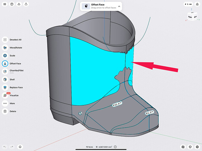
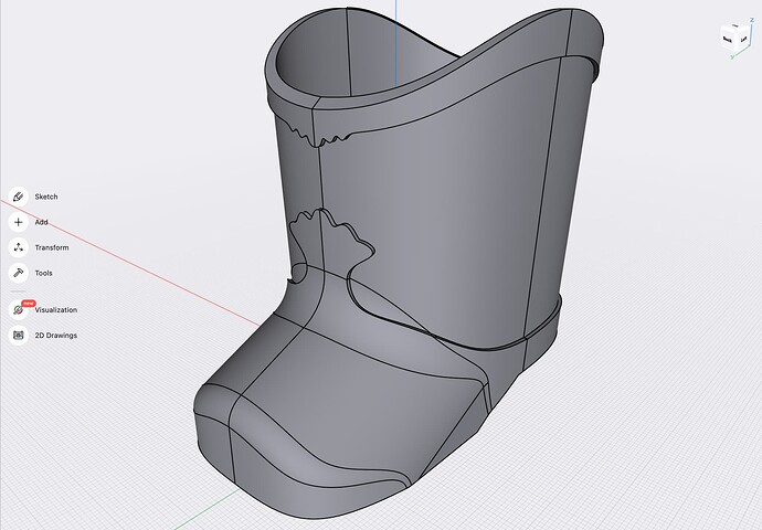
I design and 3D print accessories for doll collectors. I’ve done several shoe types where I’ve offset some faces to create raised detail. Usually these faces are created by projecting sketches onto the base shoe shape (stripes on a tennis shoe, saddle on a saddle shoe). But with this new boot, the faces are not offsetting correctly or at all. Most of the time it outright fails, then others it drags the whole shoe shape or does some weird inverting of some areas. I think some of it might have to do with the fact that the toe tip and the area between the foot and leg are still filleted areas with radii associated with them. I was able to get the rim around the top of the boot to offset, but not the designs on the back or the toe/front of the boot. Is there a way to essentially “rasterize” the basic shoe shape, then project my sketches so that the filets don’t interfere with what I’m doing? Or is there a better way to accomplish what I’m trying to do here?
I too have some situations when extruding raised details from a projected surface. Here’s an ‘out of the box’, or should I say ‘out of the boot’ something to try.
First, I would exit the project and make a duplicate and try this out on the duplicate if you think it’s worth even trying. Copy-Move the boot forward by the amount you want the raised relief to be and do a Union. (Maybe using Scale is the way to go, not sure.) Then try extruding the opposite surfaces inward. This is essentially doing the relief in reverse. Not sure if this will work nor how it will affect the surrounding area. Anyway, it might spark another idea from others.
Thank you. I will give it a try, but I’ve already tried to completely remove the unraised areas in hopes of manipulating the ones left and also I’ve tried to negatively offset the unraised areas, making the others “raised”, but neither method has worked.
So, you’ve already tried that. Another approach would be physically remove the front part of the boot after making and hiding a copy of it. Then see if Scale could give you the raised relief. If this works, it might be necessary to initially have the projected lines a little smaller due to the scale enlarging.
Hi,
I encounter this kind of issues several times.
It occurs when spline lines on the sketch have control points too close to face limits. One solution is to move a little bit the control points before doing the projection. As a rule of thumb, control or spline points closer to 0.01mm of face limit will cause issue.
Here is a short video to illustrate the point.
This is great to know and I will try to fix the curves so they avoid other lines, but there is no way to avoid the center line of the boot toe or the center back of the boot for example if I want to have a symmetrical design. Is there no way to clear the shape of extraneous lines once it is finalized?
Heather
Nothing I’ve tried is working. I simply can’t offset anything around or including those filleted areas on the front of the shoe.
Hi,
I didn’t understand you were projecting on filleted areas.
But I may have a workaround : simply create a mid plane and split body through this middle plane before doing the offset face, then union the two half.
That looked so promising and I had such high hopes, but it still isn’t working for me. The radii of the filets are still showing up (photo 1)- it allows it to offset face - but really that is just shifting things around - it doesn’t pull out just the highlighted faces (photo 2).
Here is my file very pared down if anyone wants a go at it.
Thanks for sharing. Here’s another off-the-wall approach. Here I extracted the detailed toe separately from the entire boot. After that I experimented with a slight scaling up by 3-4% and move the toe forward by 1mm. Given your final result, this might be an adequate workaround. This means the initial projected detail may need some up front mods to accommodate this approach. Sorry, I had to increase the speed so it would fit under 10mb. @PEC, your turn!
-Mike
Thank you Mike. I may need to go with this approach. I don’t like that all the edges aren’t even and I’m not sure how it will interact with the sole I already made, but if it is the only way I’ll need to make a work.
If anyone else knows why the areas won’t simply offset, please let me know.
Heather
@Mike and @heatherltn
I take the challenge ![]()
Basically, you have to split the body among various planes in order to perform the face offset, because the initial geometry is very complex locally.
2 cut planes are obvious, the 2 others are less evident : one is rotated 60° around the Z axis, the second one is place to cut the large fillet without intersecting too badly the other edges. I draw the line on the right view from (-2,+3) to (40,30) mm and create the plane through this line, rotated 90°.
Project the shape on a front plane, edit a little bit the line, clean the body from the previous shape and project it back.
Then, the face offset works quite well, just be careful that you need to select at least the right minimum number of faces before doing the face offset :
- for the first one, only one is required
- for the second one, don’t forget to select also the front face of the boot or you won’t get face offset on the front face, so 2 faces to select at least
- for the third one, you must select at least 2 faces
- for the last one, you must select all the faces or it would fail.
The remaining is easy: union the 4 bodies, mirror to create the other quarter of the boot, union, and union with the rear of the boot, and that’s it ![]()
Hope it helps.
PEC
I think @PEC 's solution is more exact and mine is more of an approximation. Here I added a new step that will make the sides a little cleaner. After subtracting the back half of the boot, I projected the side profile to the plane. Next I subtracted the side where I want it cleaned up and stopped it where the front curves up. Then, as before I scaled it up by 3% and move the tip forward by 0.5mm. I made it orange so you can better see the result. So, you have a couple of choices- one is quite exact and the other is more of an approximation. Good Luck!
-Mike
Wow! Amazing. Thank you.
Heather
Mike, this is a great clean up of the first solution you gave.
I actually worked in this after getting your first scaled up solution and came up with something I was happy with - except for that same area you corrected. I came to live with it anyway and it doesn’t show up too badly in the prints. If I do redesign it any in the future though I will make that change. Here is my finished piece:
And thank you so much Mike and PEC for your help with this design! I greatly appreciate it and I learned so much with this project - definitely my most complicated to date.
Heather
The new boot looks great. Nice job with stitches too!
I’m curious, what 3D printer do you use and what material do print with?
Thank you Mike. The stitches are time consuming, but worth it I think. These boots were printed on a Creality CR-6 SE - no mods - at .2mm layer height using cheap 3D Solutech PLA filament - this navy blue color is very metallic compared to many of their colors (even though it isn’t listed as a metallic/silk). I use 3D Solutech and Fila Cube brands for most of my colors, both pla and pla+.
Heather


