Shapr3d has a beautiful interface and has amazingly stable extrusion and Boolean operations.
I have am just getting into how this system works. I understand the concept of planes and projecting elevational line work. But… to make a simple hull shape for a boat or kayak is a nightmare! I have drawings and a converted model I am working from and need plan, end and side elv to create an accurate shell structure. I also need to accurately show the position of the stingers, gunwales and cross sections and their joints. The lines around the hull will need to be converted to extruded solids to represent the shape of the wooden stringers. This can only be achieved by allowing a spline to shift in x,y,z space. To sum up. I would like to create a solid shell and a second model underneath that can have the splines converted to solids that follow the Wooden construction.
The only way I see this being created in Shapr3D is by using the lofting or sweep options. This only allows me to use multiple extrusions along one path direction. I cannot combine the plan or side elv, only the end elv which the loft or sweep is created.
I have tried using multiple projection planes for each intersecting point, but that is a crazy way to do this?? I don’t understand why xyz points and curves cannot be connected. Even the most basic of 3D modelling apps can do this. There are so many applications for cross elevational modelling. Design a plane fuselage, kayak hull, roof designs etc. They all need joining points connected directly to x,y,z. For the sake of stability in solid modelling, I would hope that something as crucial as this would not compromise an essential modelling technique used by millions of engineers.
If someone has an easy solution or an example of a hull created using multiple elevations, please let me know. This should be a very simple process. I have invested my time and money into this subscription and thought this could be a good alternative to other systems. I hope I have made the right choice. Any help would be very much appreciated. Please see the attached image of a model which I am trying to create a skin for.
Thanks for showing my your fuselage. Unfortunately shapr does not control splines in x,y,z to make interconnecting faces. I need to be able to create the shell using the splines but also use those splines to create the solid frame. The shape of the splines are important. I cannot see a way to use the splines created from the solid to form the frame. Please see the example picture. Thanks for your help.
These are some suggestions regarding achieving your objective. S3D often has multiple routes to the same result.
Lofting as suggested by @JST just needs the Profiles of the Design to be set out along the Keel Line and for the Bow and Stern Profiles to be created from the inner faces of the respective timbers.
Lofting will create a Solid Body that could be Tools > Shelled to create the Skin.
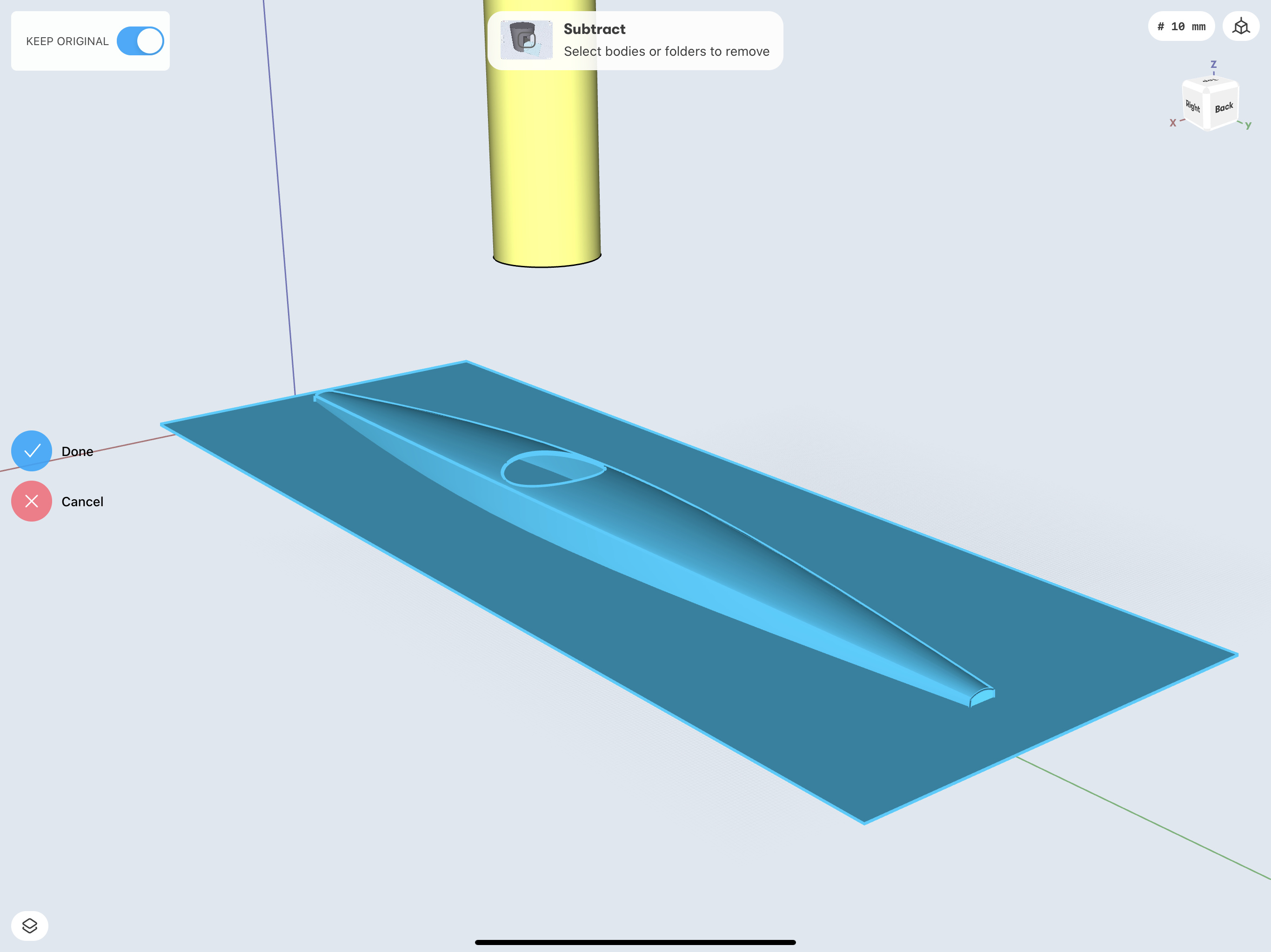
The Access Aperture could be formed by Tools > Subtract by creating and using a ‘cylinder like’ Body.
This uses only 3 Profiles, is Shelled to [IIRC] to 6mm Thickness and used a simple Cylinder to for the Access Aperture:
Uniform Section - Tools > Sweep the appropriate Cross Section Profile of the Timber along a Curve
Non Uniform Section - Tools > Loft along a Curve
Add > Construction Plane was used and given a thickness of 0.001mm to form a Body. Tools > Subtract and Keep Original [switch at top left].
Positioned appropriately this was used to create a Horizontal Cross Section to provide the Curved Edge that can used to create the Stringers. Of course the Stringer Profile will have to be positioned to accommodate the Skin Thickness:
Hi Gelphyn. Thanks for your input. Really appreciate that. The stingers you have position along the plan appear flat? All of the stingers/line work are running through various curves along the side elv.
How do I follow the curves or extrusions in both elevations? A boat hulls stingers require transition between all elevations. Splines that move in x,y,z. Any help is very much appreciated. Please see the side, Elv.
@MASV
In my Design the the outer face of the Stringer matches the Profile, this is difficult to see even if you tap the ScreenShot to expand it.
As suggested:
This is doable but by no means quick and easy.
I would be inclined to follow the idea regarding Horizontal Cross Sections and apply it to the Vertical Cross Sections. The latter could be used to create the Stringer Section Profiles.
Worth trying because Loft works extremely well and may transition better than you imagine.
Re: Access Profile Support Timber:
The task of creating the Support Timber for the Access Profine could be achieved as follows;
First Duplicate the Design and work on the Copy.
In this the Base of the ‘Cylinder’ was used to create a Plane for a Sketch, the inner Circle is the Aperture Support outer dimension and the outer Circle set to provide cutting the Support Timber.
Selecting the Closed Sketch Ring shape drag the Double Arrow downward in one movement.
Hide the unneeded Bodies:
Thanks Gelphyn. I really appreciate the time you have put into answering my questions.
Unfortunately the design of this kayak needs to conform to the stringers running in xyz. The hull shapes fluid dynamics would be effected and the construction of the frame would not work if engineered using straight profiles. This kayaks frame is to be wrapped in hi density Dacron. The outer shell or solid form is just for visual reference. The real work in this model is the actual framing. I modelled this wireframe with ease using Viacad 2d/3D. I might have to continue modelling this in VIacad. There does not seem user friendly solution to archive this. A shame really as I think Shapr3d has huge potential and I will use it for various future projects. I have been using this app for about 3 days. Was very impressed with the speed of extrusion, Boolean based modelling. Made the chainring model bellow in about 1hr. In Viacad that would have taken me some considerable amount of time. So I do consider this a viable modelling tool. just needs some work. thanks heaps.
I enjoy trying to solve problems that have never presented themselves before.
One of the S3D Team many be able to chip in.
Hope you achieve your objective. Stay safe.
Found a solution for half the problem. For the stringers and framework along the side elv and plan, I used a small square cross section multiple x, applied translate to the edges of the solid and then lofted along the edges. Not perfect but will do. Still need to workout the rest. I’m finishing up for the night. Cheers.
Tried the sweep option across edge to loft but if went off axis. This solution should work. Will try and sort the other stuff out over the next few days. Just wish there wasn’t so many work arounds. Cheers
I was working with the End Section Profile [both the same in this case] and the Edge of a Horizontal Plane.
The outer edge of the Stringer Profile was modified to match the End Section Profile.
Used Tools > Sweep to form the Stringer.
Something must be out of alignment if it went off axis.
A Tools > Loft would be kept on course by the subsequent Profile(s), provided that it was correctly positioned.
Sleep on it and start refreshed tomorrow
I’d love to see how you made that gear in about an hour. I’m not doubting you, I’d like to learn as my goal with S3D lies along these lines (mechanical parts which interface with things like chains and gears or other moving parts).
The sprocket shape for instance; it looks like perhaps a wedge shape with a circle subtracted and then repeated. The central mounting hole keyways are another area I’m interested in learning how you got it done in S3D.
Would you be able to spare some time to help people like me to learn how you approached this part?
No problem, sure I can help you out. Haha, Although I’m new to SHapr3d also and might steer you in the wrong direction. :). Yeah, the chainring was only a test model to see what I could get out of S3D. It’s rough and I didn’t spend much time on accuracy.
Only difference i have is 26+ years experience in modelling among other specialised fields. I have worked in the visual effects industry, post production, design and manufacturing most of my career. Although do little design work these days. I know work part time as a life coach for special needs adults. Go figure. will see if I have any screen grabs of the process and talk you through it.