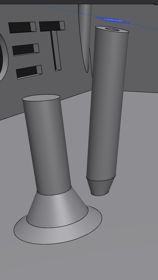
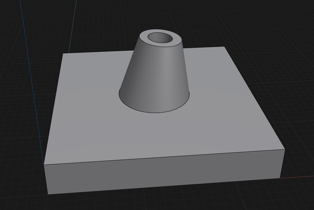
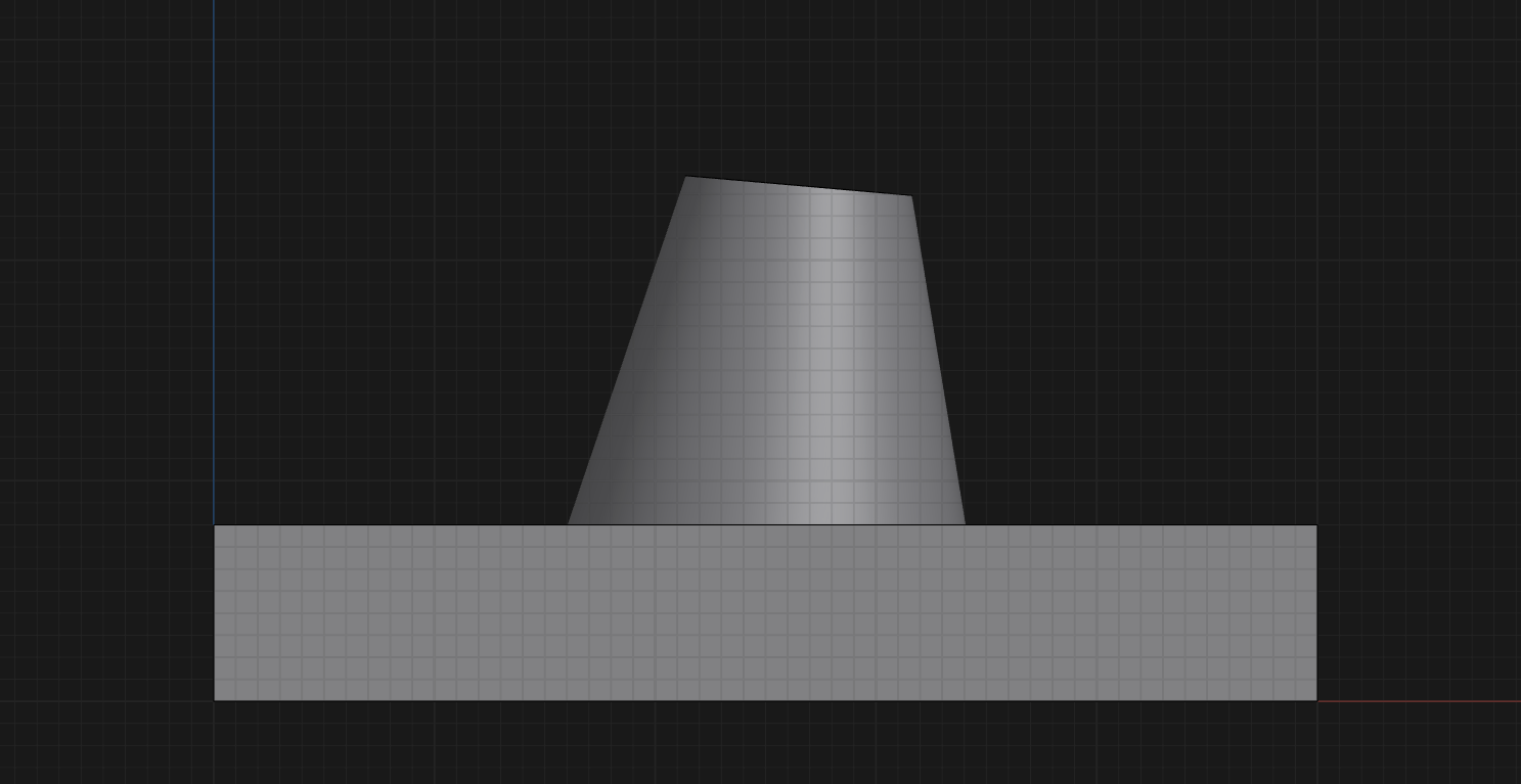
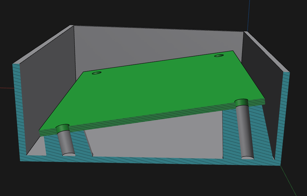
I’m creating a box to be 3D printed for my TEC-TEC-1G project. I have some mounting holes for the PCB and under these I want some supports. Managed to get those, but now want to add extra bracing/webbing so make those stronger. In the pic below, I was hoping to make it basically a cone shape, with the circle I’ve drawn and selected to be the base of the cone.
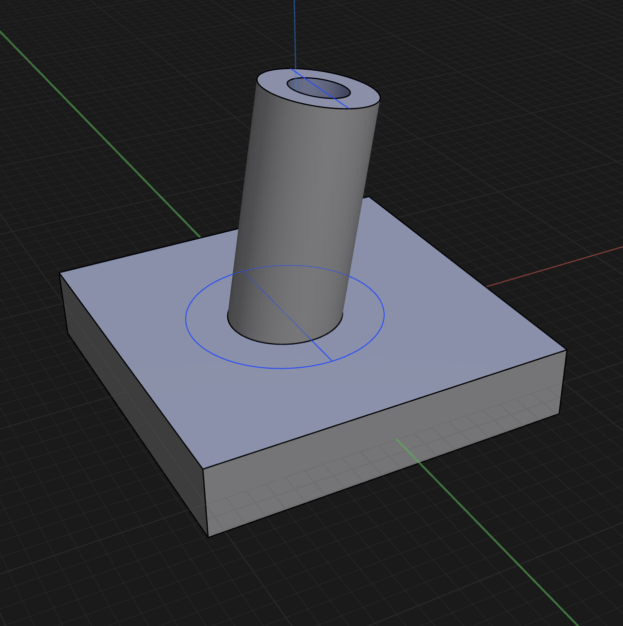
I tried using the LOFT tool, even watching some YouTubes on how to use it, and it simply does not work, with an error appearing saying it wasn’t valid. (I was selecting the big circle on the bottom of the box, and the circle at the top of the support)
Is there a better way to do this? Happy to watch some YouTube on a specific tool if you can give me links or point me in the right direction.
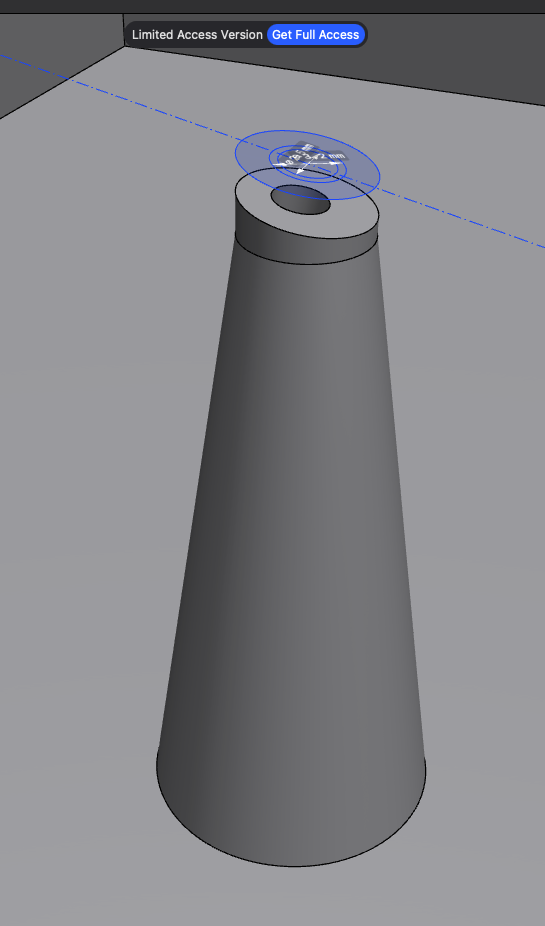
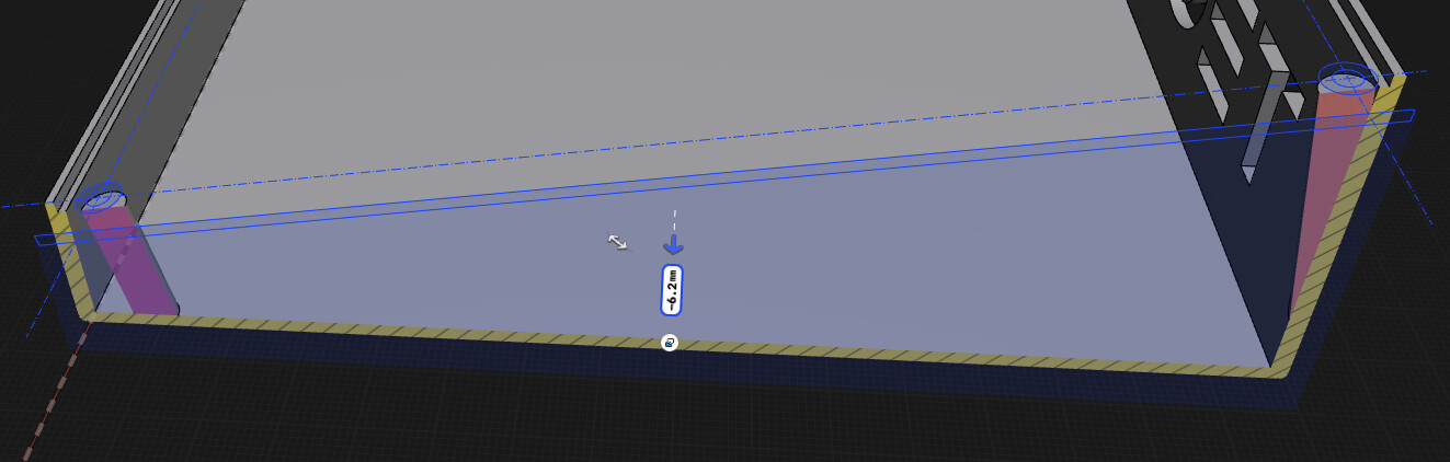
That is perfect! Except I’ve obvioulsy built my model incorrectly. When I create the shape you have, I can use that double fillet on the cylinder I made next to my support. However, when I try it on my angled support (it is perpendicular to the PCB) it takes away a cone, rather than creates one. I made the tube from the PCB by daraying a circle then pulling it down till it touched the bottom of the box. Obvioulsy I’ve done this wrong. Maybe I have to make the cylinder, starting from the bottom of the box, then tilting it over 10 degrees (what the PCB is at) and then try to centre it to the mounting hole in the PCB?
Yep, when I create two circles in the middle of nowhere, loft is working exactly as per you videos. but not on my supports which I must have created incorrectly. Not sure how I should have created them, though… Bu I’ll tinker till I find a solution. The hard part is going to be lining up the supports with the mounting holes in the PCB, I think. Just dragging the circle down from the PCB is obvioulsy the easy looking, but functionally incorrect way.
Oh I don’t have a problem with removing the hole for the loft, and then putting it back in… That’s easy. But I just don’t think I’ve gone about making the support correctly, in the first place. I created them from the PCB and pulled down… Not from the box and pulled up. The problem being that the box is flat, while the PCB is on a tilt of 10 degrees. I’ll keep tinkering… Only just learning this program. Still not purchased because not 100% sure my brain will work the way it does. I’m more of a TinkerCAD type of brain: Make shape - pull or push different shape into it to add or subtract. Shape becomes normal Solid. Simple. Shapr3D - not so simple and I’m obviously breaking rules it doesn’t like.
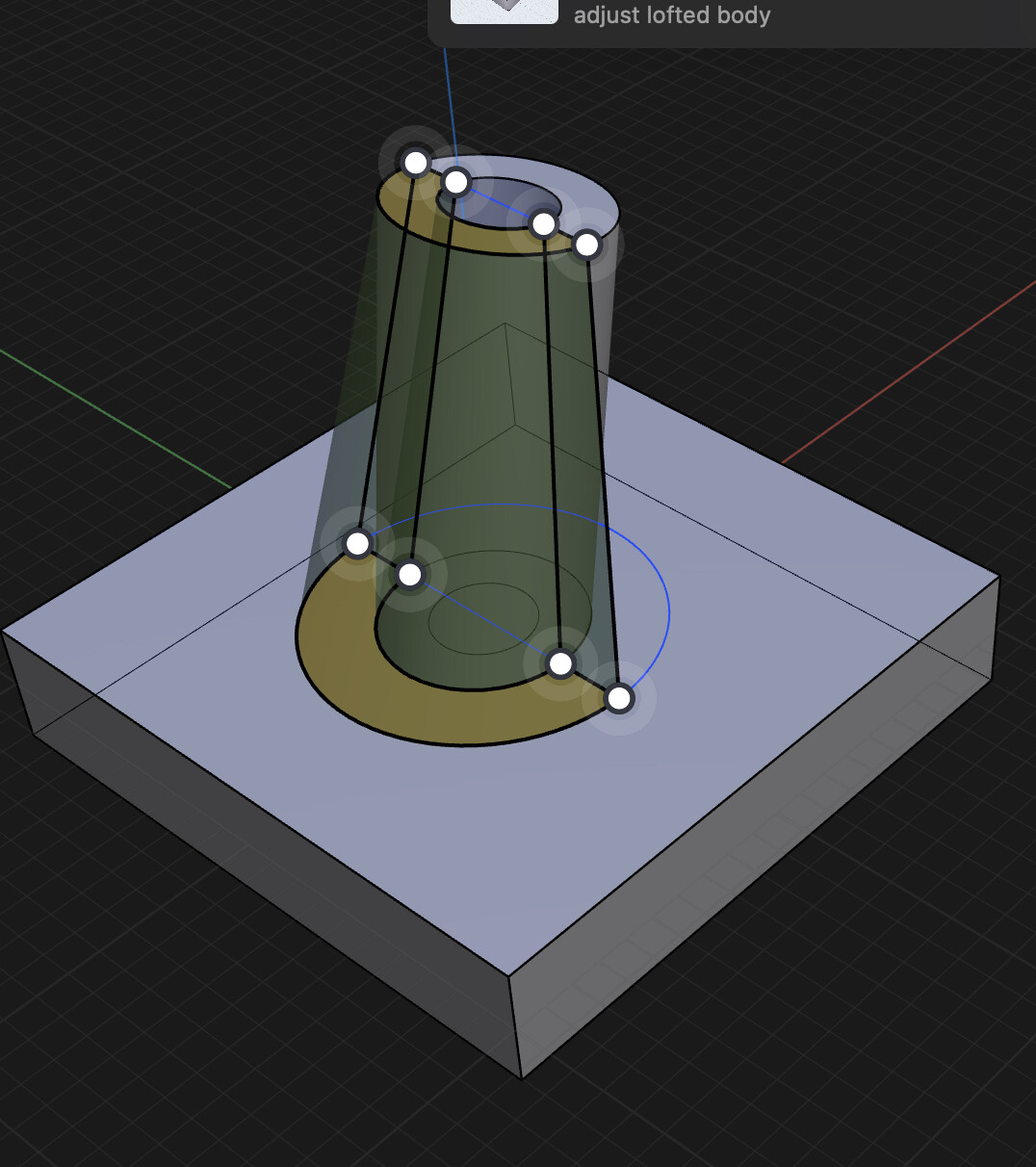
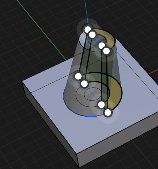
Ahh… Nope. LOL! Didn’t know that was a thing, but now that you say it out loud, and having just tinkered enough with it (pulling it up from the box floor, then doing the fillet, then rotating the top circle 10 degrees to match the PCB, then projecting the PCB hole onto it, then pulling a drill hole down)… It makes complete sense and yes I was doing it wrong. LOL!
I got it in the end, although the top of the support isn’t exactly a perfect circle… But it’s good enough.
Thanks to everyone for your explanations and apologies for my noobness.
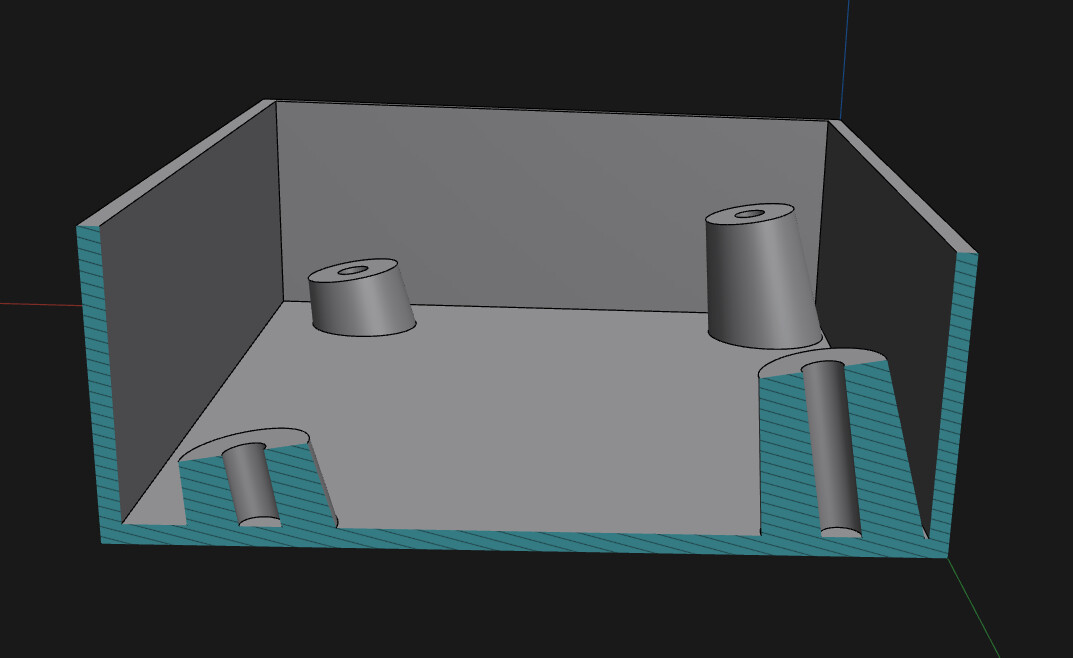
You don’t really need to do a lot of extra steps. In the video, I show a quick design of a box with a PCB. All the supports for the PCB were made with just one action in the history — and they’re already angled, coned, and have holes. Plus, they’re perfectly rounded. They’re also united with the box, but not with the PCB — even though I started from the PCB side.
Not bad, but… the fewer actions you use, the easier it will be to make changes later. Maybe it’s just me, but I don’t like a messy action history or item list.
There are a lot of videos on Youtube. You can start from official Shapr3D channel.