Hi, I’m new to shapr3d, though I’ve made different simple models before. Now I’ve been several hours trying to make this work.
I need to create a seamles curved 90° corner between 2 objects. The basic shape is the same except for measurements. One is slightly longer or deeper than the other. So I’ve been trying different methods, but it looks like Loft is the way to go. Found out how to use the arc and the spline to follow the curve, BUT when selecting some specific ones, it gives error. I have no idea how I can solve this, in theory I need the upper top corners to be 90° without a curve, but no idea how to achive this using the Loft tool - Also when I select the shorter/smaller arc towards the circular axis (or where the 3 axes meet) the tool says immediately that it would be an invalid object . no idea why. And when I try to anyway create the object with Loft, then it gives that error (Operation failed because the resulting body wouldn’t be valid).
Hope anyone can direct me to the correct way to generate this object. Basically is a "translation- or expanding with a curve though I know some points won’t be exactly 90° as the length of the central parts of both elements change slightly.
thank you in adv
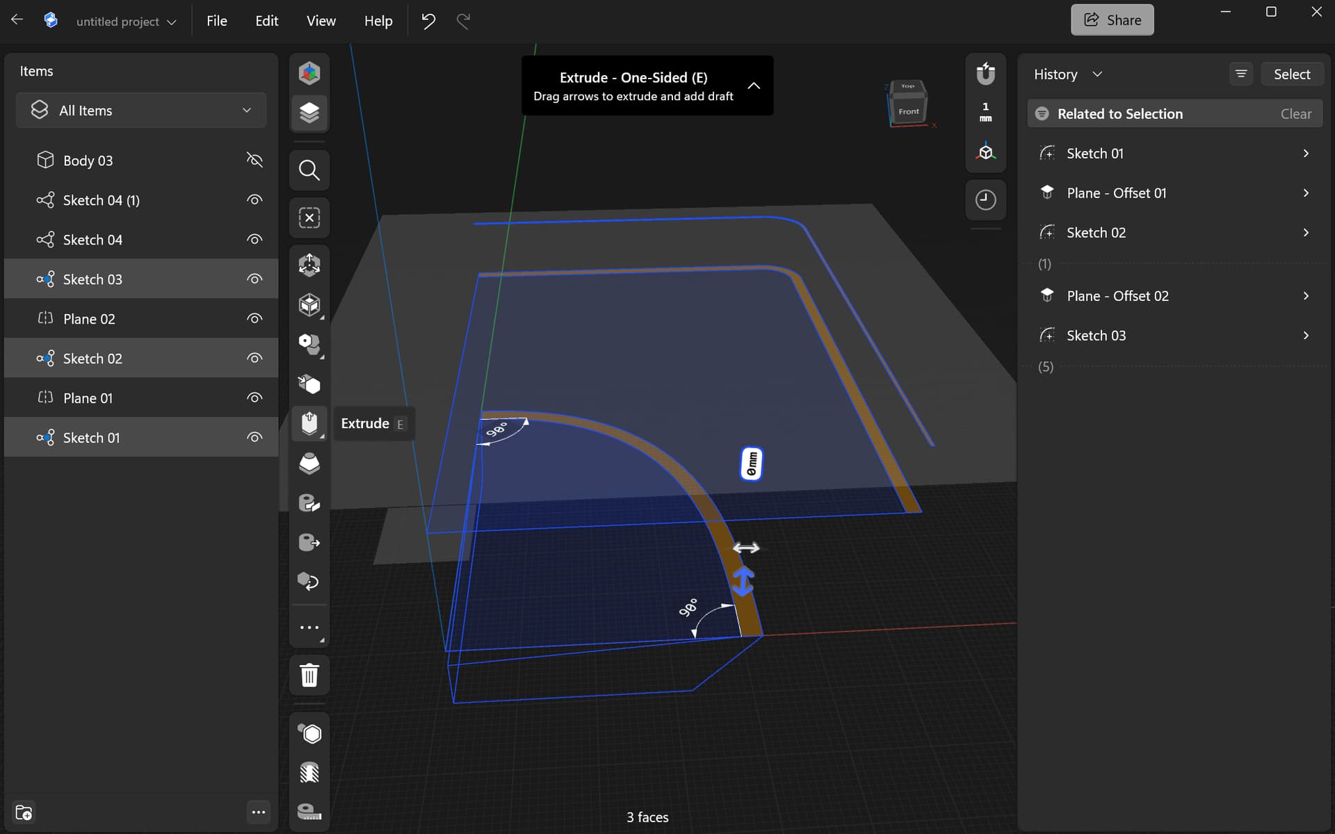
Here are some screenshots.
The message “would produce invalid object” usually occurs during lofting, when the lofting path (line) is not actually snapped to the start and finish shapes.
You will need to create multiple horizontal sketches using the add sketch plane tool.
When you create a sketch on those planes the points at which the vertical sketches intersect are usually marked with a point that you can snap to.
Hi, thanks for your comment. I noticed the snapping points. I did move the arches points to snap to the sketches. Still shows the error. I will check again carefully to make sure the points are connected.
Hi there
Thinking about your issue, and having a little time over the weekend.
You will do better if you think about your shape in horizontal layers.
Then use loft to join the shapes in a vertical direction, instead of along a rotational path.
The LOFT function tends to struggle with rotational curved paths.
In the picture I used two vertical lofts to do the sides and one rotate loft for the base. Then boolean together.
Here is another picture with the lofted shapes vertically.
Don’t forget you can produce other bodies on their own, then position those to perform boolean subtractions to make the cut aways in the base part.
Hi thanks a loooot for having a look at this problem. I will give it a try thinking horizontally, but I’m not sure how to create the ridges on the lower part of the figure I need to create. My thoughts to do the loft vertically and following the curve is precisely because of thie ridges and that I don’t know exactly how to calculate the curve angles. Will try different approaches and let you know if this thing works in the end or not haha. Again thanks a lot! Attached the screenshot with the main figures I need to loft/expand according to the curve.
Have you thought of a sweep instead?
Yes but the 2 ends of the final figure are slightly different, that’s why the “problem” arised, as the part between the ridge and the higher vertical part, have a different length. Thanks for looking into it
I see it now, could you post your sketch? I can see what the fix could be, you might need more guides on top of the of your model.
Simplified sketch.
I believe it requires 2 separate loft.
Thanks a lot, it seems I’m getting there.. Horizontally I couldn’t solve it, so I decided to extrude the “end” shapes, and then cut vertically and I’ve been lofting those.. It seems I have a slight height difference, obvious when thinking about the horizontal angle (it is to let water slide/drip towards the center). So at a specific point, the height is different. It looks like it is ONE single point haha. I’m getting there! . The next problem will be to make the slanted “upper” surface with a nice curve towards the center point to where the water should slide. So the “corner” point or the confluence of the 3 axes… if you get what I mean.. but that will be the last bit to do.
Thanks everyone for the help. I’ll post when I get it done, or scream for help again haha 

Knowing that you want a fairly square top corner with a smaller radius than the bottom.
keep in mind, multiple lofts will not perfectly align the face curves and you get ridges or valleys at the intersections.
When you come to do the vertical lofts. the first one might be best from the bottom of the model to where it becomes vertical.
You want your vertical loft to overlap the bottom body, so that you can boolean them together. This way you will get a nice smooth surface around the outside.
This is not a problem for the top part as it joins to the sloped wall with a ‘chine’ (as it is called on boat hulls)
You are correct now looking at the backside, you get the ridges even thought it just straight edges. Might need more guides, but that gets overly complicated.
I found this issue on that problem with the shipping container corner.
Loft struggles with curved paths.
Lofting vertically seems to be more productive for the wall part of this shape.
Thanks everyone, I’ve been playing around whenever I get the chance, and so far I’ve come to this point. I was thinking, now that I have the “basic” horizontal shape, I can try recreating that one lofting upwards (vertically I mean), then join with the vertical part that extends towards the top - If you know what I mean or if I explain myself rightly (english is not my mother language and sometimes I struggle generally with explaning stuff on any language hehe)
So I tried cutting the main “exterior figures” let’s say 1-left-wider / 2- right-shorter.. and lofting each piece, then appliying union whenever possible. I’m not familiar yet (I know I have to learn more) about boolean calculations and operations, so I’ve got of “boolean errors”. but at least I got something I can maaaaaybe work with.
I’m using the free Shapr version, also not too happy that the stl generated are not at a good quality, so I’ll eventually will have to rebuild everything somewhere else (I need to learn Fusion I think? - 3D printing newbie problems hahaha) -
So I’ll keep trying- The whole project is to create a half border around my kitchen sink that couldn’t have been worse designed. Its left side has less than 5 cm distance from the wall, with a slanted worktop border (at 45°) and leaving barely 2cm of the wood between sink border and the slanted border. Annoying as hell, gets full of water when dishwashing (not a dishwasher owner, no space). The back side (equivalent to the “1-left-wider” side) has 5cm, is a total of 8 cm from wall to sink… and allows me at least to place there the soap bottle, etc. Minimal space and gets flooded, Hence the need to make some kind of small L shape platform to place the stuff on front and allow the water to slide to the sink. I did a test before, a simpler solution (without the raised part that will be stuck on the wall), but the water runs from the tiles of the wall behind the 3D printed platform, but at least the main purpose works, and the flooding stopped, so it is less water accumulating (and molding).
Anyway, felt I needed to explain the use of it haha, as it is such a weird figure, in my creative designer’s head of course I see the object clearly, but as a learning 3D modeller I’m puzzled about all the other problems that arise from creating a 3D complex shape. - Thank you all so much for looking into it!


if it makes sense this would be more or less the visualization of “final” model. Still will need grovels alongside the extended parts and one on the corner to flush the water towards the sink.
If your thinking about transferring software look up other Parasolid based 3d CAD software like Shapr, your crash course will better transfer.
Unless you can get good online discount for Fusion, Shapr is still the cheapest. Shapr only export low quality for the free and high quality for the paid subscription.