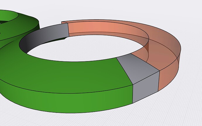
Thank for you for the video PEC. Yes this is how I managed to get it working - after having to rebuild the model from scratch.
I think the issue I explained/demonstrated in the original post still exists (and repeatable, please try splitting the body and try lofting the ‘Issue Part.shapr’ file above);
The faces appear to be in a certain position (in this case, edges that are ‘0.0000mm’ from each other) are actually not EXACTLY 0mm from each other, as they have been shifted to this position, using the Move command. So when other operations are carried out on them, such as a Split Body command, they behave strangely, moving around slightly, which causes the subsequent Loft command to fail…
I would normally say that this is not much of an issue, as in my typical workflow (Siemens NX), most items are generated and automatically updated from a sketch, so it’s simple, just quickly update the sketch, and the revolves and the rest updates… However with direct modelling, where bodies are not linked/updated from sketches, and users are encouraged to modify and adjust bodies that are already existing (hence, direct modelling), I believe this is quite an issue/challenge to avoid downstream commands failing…
If the method of adjusting faces (move/offset) aren’t robust or accurate enough, then every time I want to adjust a feature that has been lofted and blended, I have to;
- subtract/delete the existing body
- make a slight tweak to a sketch
- generate several new bodies
- boolean them
- loft them
- chamfer/blend them
… this is not efficient, and takes a relatively huge amount of time, and takes away the benefits of direct modelling. It makes a lot of sense to be able to easily adjust the faces or edges so they align, without having to have sub-micron (<0.00001mm) discrepancies causing subsequent commands to fail, or having to rebuild the model from scratch.
(especially vs linked sketches/parametric modelling: 1) update sketch, 2) the rest updates, provided the changes are not too extreme)
I think there needs to either be;
a) A tolerance on features such as loft, to avoid them failing. I’m talking pretty small here, bearing in mind the edges were measuring as 0.0000mm apart before ‘jumping’ apart during the Split Body command. This should be possible using the Siemens Parasolid engine, such as seen on the commands in NX;
b) To have more precise control or snapping when direct modelling adjusting edges or faces using Translate/Move commands. Translate is good, but I have not been able to select centre points on anything but primitive geometry (cylinders, cones, etc.). In this case it is the centre point of the edge/arc that I need to select, so that I can truly align the edges of the green and orange revolves.
Also, having the options of what to snap to during Translate might be quite useful,

like in the sketch environment - but in 3D, after all, modifying 3D geometry is what direct modelling is all about!
Anyway I love the program and continue to use it whenever possible for simpler components/smaller assemblies, please keep updating it. It’s soo close to displacing full-size CAD for component modelling, just still a few frustrations that have meant modelling takes quite a bit longer than necessary.
So, either adding snapping for aligning 3D objects (i.e. a more powerful translate tool, that can snap to; arc centres, midpoints, intersections, quadrants, etc), or a tolerance (say 0.001mm?) on more complex commands like loft would save a huge amount of editing/rebuilding time, and allow direct/synchronous modelling to be a lot more powerful and accurate.


