Hi,
Here is a fully parametric gear generator, with variable defined helix angle, teeth number, modulus, pressure angle, backlash, teeth offset, gear form factor, number of fillet per turn for the worm, etc. ![]()
Variables defined helical gear v2.14.shapr (11.8 MB)

The generator creates left and right versions of the gears, either centered with one tooth aligned up (for 3D printing or exporting into other projects) or meshed together and “animated” with the “rot” variable to check for functional interferences.
Worm is created only when helix angle beta is not zero degree. When beta equals zero, gears are spur gears.
Video below demonstrates most of the features.
The key thing to understand regarding helical gears is the fact that helical gears are defined using normal parameters but are drawn using tangential parameters.
Normal parameters are measured in a plane perpendicular to a tooth while tangential parameters are measured in a plane parallel to the side of the gear.
To try to visualise things, it is helpful to remind that a gear can mesh with a rack, so the gear and the rack share the same parameters (pressure angle, modulus, etc). We could manufacture a gear using a (sharp) rack as the tool:
- slide the rack to “cut” one tooth
- rotate the gear to be manufactured by 1/10 of the tooth
- translate the rack by 1/10 of the pitch
- repeat the process

For spur gears, normal and tangential planes are equal because the teeth are perpendicular to the side of the gear.
Now, using the same exact rack and movement, we just rotate the rack around the vertical axis by an angle beta : we get an helical gear with an helix angle beta.

Because we are using the same rack, normal parameters measured perpendicular to the rack’s teeth are exactly the same as for the spur gear, because the rack has not changed.
This is the reason why helical gears are defined by normal parameters.
But the angle beta by which we rotated the rack changes the tangential parameters measured along the side of the gear: as a result, we must compute the tangential parameters to be able to sketch the helical gear, and we can now do it with variables and expressions.
There were a few challenges to solve in order to create this generator.
-
First challenge was to keep the history clean (error free) whatever the parameters’ value (25 parameters, 50 computed variables and about 100 history’s steps
 ).
). -
Second challenge was to automatically delete the worm when the helix angle Beta is null, because in theory worm cannot mesh with spur gear without backlash. Not so easy without boolean variable nor conditional step’s execution.
-
Third challenge was to recreate trigonometry functions (sin, cos, tan, acos, atan) with enough accuracy using Taylor’s series, and was a good test for variables. Here is an exemple

theta1_ba = r2d * (Pi / 2 + d1_b / d1_a * (-1 + d1_b / d1_a * d1_b / d1_a * (-1 / 6 + d1_b / d1_a * d1_b / d1_a * (-3 / 40 + d1_b / d1_a * d1_b / d1_a * (-5 / 112 + d1_b / d1_a * d1_b / d1_a * (-35 / 1152 + d1_b / d1_a * d1_b / d1_a * (-63 / 2816 + d1_b / d1_a * d1_b / d1_a * (-231 / 13312 + d1_b / d1_a * d1_b / d1_a * (-143 / 10240 + d1_b / d1_a * d1_b / d1_a * (-6435 / 557056))))))))))`
Some technical documentation is embedded into the .shapr’s workspace using images, as a substitute to notes.
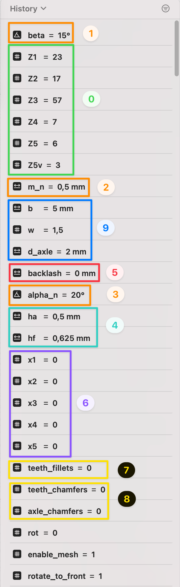
Parameters’ definition:

Equations to compute the gears:
There are some interesting things such as is_beta_null variable, which is a -crazy- way to overcome the miss of boolean variables, or the addition of 1e-6 deg to gamma variables to force revolve tool to operate as extrude tool when beta is null, because we do not have conditional execution at present.

Gears’ parameters


Rack’s parameters

Worm’s parameters

Helix angle Beta: from spur gear to helical gear
Worm: impact of number of fillet per turn

Meshing with 0 backlash

Pressure angle impact on teeth’s shape

Teeth number impact on teeth shape

Backlash variation

Teeth’s offset impact on teeth’s shape and gears’ center distance
-
sum of offset equals 0 : no impact on centers distance

-
sum of offset not equals 0 : impact on centers distance

Teeth offset can solve functional interferences when low teeth count

3 points control spline computation to approximate involute of a circle