Hello, I have a problem making a part with very precise tolerances.
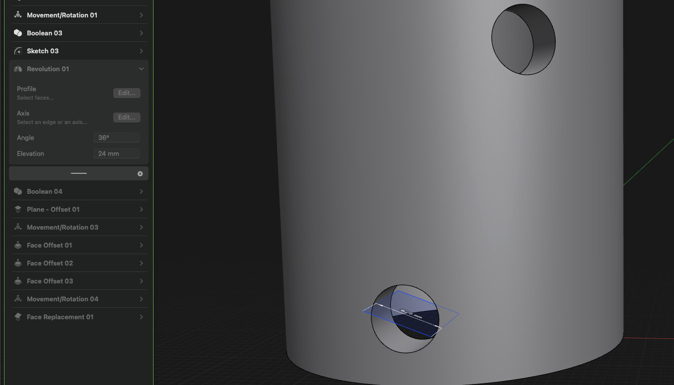
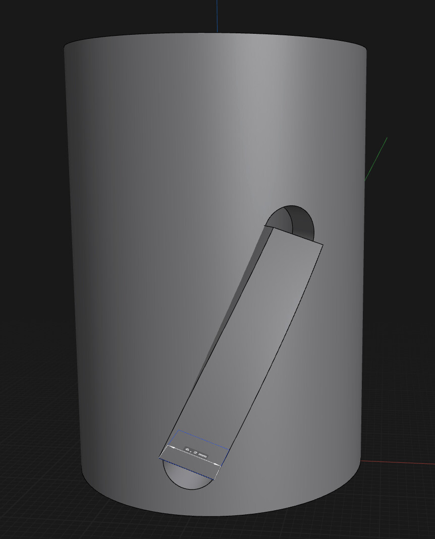
I can’t build the gray part guide to create a 36° rotation movement for a translation of the red axis of 24 mm high.
The yellow axis must remain in contact with the two surfaces.
Can someone explain a method to me? Thanks
I was asking myself the same question… I made some visual corrections to find the best angle, but the solution works well, more than enough to create a prototype with my 3d printer…
Here’s a somewhat precise method. My slot is 4mm wide and the rod that slides up the slot is 3.6mm dia. The rectangle used in the revolve is rotated 54° which will be normal to the 36° angular slot that is 24mm high. After the revolve I added 2mm length to each end t compensate for the diameter of the 3.6mm rod. Hope this helps.
Quite interesting. I used the same method, which I explain above, but to get precise result had to rotate rectangle on ~68 degrees. Only difference I have 6mm width slot and 6 mm rod.
I too tend to eyeball designs (meaning examples). I used an intuitive approach on this one getting the 54°.
Each rod is copy elevated 6mm and rotated 9°.
Note, my first post said ‘somewhat precise’.
I made a precise parametric design some time ago to do this kind of slot so I share it here.
It is accurate even for large values of the helix angle and thick tube; it also handles clearance.
You just have to set 7 variables: