Here is how I’d do it. There is nothing wrong with @Bob3DPO’s solution, but I noticed your cutouts are rounded and I think that’s a bit harder because it’s not straightforward what’s gonna happen with them. As they go to the middle of the lampshade the radius of the pattern decreases so you need to decide to keep the depth or the ratio. Former means the width of the cutout is gonna be very small at the end but you wanna keep the depth so those waves or circles are gonna be transformed to lines basically. Latter means you wanna keep the ratio of the wave consistent across the surface so in the middle there won’t be a cutout at all.
I show you how I’d do the first version because that’s visually more appealing to me:
- Use the front (XZ) plane and draw the spline of the outer surface and use the offset edge tool (in single mode) to make more splines. You can think of the edge tool as the 2D version of shell tool basically. Here I moved it by 8mm, 1mm, 6mm and then 1mm, that’s 16mm overall what will be the thickness of the lampshade. I chose bigger values because it’s easier to see it on my screenshots but you can divide these numbers by 8 to get the thickness of 2mm at the end.
- Rotate the splines around the Z axis in the following way, don’t forget to turn on copy. I go from the most outer spline to the most inner spline:
- first: no copy needed
- second: no copy needed
- third: 1.125 degrees both directions. that’s 25% of 4.5 degrees what is the half of 9 degrees, 1 unit in your pattern where 40 waves equal to 360 degrees
- fourth: 3.375 degrees both directions
- fifth: 4.5 degrees both directions
I added some circles and radiuses as lines to this screenshot so it’s easier to see what I meant:
- Switch to the top (XY) plane and use the intersection points (or endpoints if you added those helpers above) to draw a spline. Now you understand why we needed all those splines in the beginning. This is gonna be one wave in the pattern. You can make a different spline but you’d need to adjust the splines accordingly, we will need them later.
- Add a construction plane. Here I added a line to the Y axis and used the through edge at angle option. On my screenshot it’s 91 degrees but maybe you need 89 degrees, depending on the direction of that angle. The plane must cut the splines on top.
- Select the newly created plane and turn on sketch mode. You will see the same intersection points as on the top (XY) plane but they’re distorted. Now you understand what I meant by having smaller radius and keeping the depth of the pattern. Draw the same spline as on the top plane and double check that every point is connected to the equivalent with the big splines.
- Now if you select both faces you created (one on the top plane and one on the construction plane) and the connecting splines you can make a loft. Now this is a bit tricky because I got an error message but I investigated this problem a bit and found a workaround. I opened a thread with my problem, I’m pretty sure it’s a bug. If you have the same issue you can use my workaround, what is basically cutting the profiles into smaller pieces.
- Create a circular pattern (quantity 40x / rotated) and move the gizmo to the origin then rotate it to the full 360 degrees:
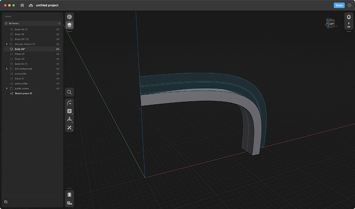
- Hide this new body go back to the original splines on the front (XZ) plane. Select the faces and the Z axis and use the revolve tool:
- Now select this newly created body along with the circular pattern (you can use the layers to select the whole folder) and subtract:
- The result is an inverse lemon squeezer:
Known issues:
-
Lampshade is too thick. As I mentioned you can change all the values (distance between splines and angles you used for rotation) but keep in mind that the loft tool needs to have intersecting profiles and guide curves. You should see similarly connected profiles and guides as in step 5. Even the smallest misalignment ends up in a failed operation.
-
That tiny piece in the middle. The loft doesn’t reach Z axis because lofts cannot end in a line or point. This is a lampshade so I guess there will be something in the middle but in case you wanna get rid of it you need to cheat somehow. First of all you can always move your end profile closer to the Z axis, I used 89 degrees for my construction plane, you can use 89.5 or 89.9 or 89.999 degrees. As long as you can zoom in to draw the end profile from the intersection points you’re good. And you can cut out the microscopic last piece with another subtraction.
-
Loft tool, obviously, I hope I’ll get an answer soon in the other thread.
-
Because I needed to change my start and end profile due to that bug(?), subtraction didn’t work for me. It’s because the new lines at the bottom of the shape are actually inside the lampshade body and the subtract operation results in an error (boolean error or something like that). The workaround is to add an extra body to the inner side. I created another spline, and revolved it around the Z axis. You can cut it first and merge with the loft before making the circular pattern or you can merge the whole revolved body with the circular pattern, it’s up to you.


