Ok is it really different??
It’s basically this if you zoomed in alot.
Ok is it really different??
It’s basically this if you zoomed in alot.
They are. TC has issue because he overlap two control points. Font has issue with wrong calculated spline. Totally different things.
Ok so explain why I can’t extrude the other part.
Holy cow! This is too cool! Thanks for sharing the tip. I’m not exactly sure how it works, but I figured a way. The key was when I looked down on the object from above and clicked on the bottom from that angle.
Thanks!
Mark
Ok so how would I use ur original method to fix this?
It’s totally different problem. Again I describe a method of identifying a problem not fixing.
To fix this problem you have to add a gap or make intersection of two parts.
So I think what your saying is you modifying geometry to make it work.
VS
Instead of fixing the parts that needs fixing?
I’m saying that issue identification and fixing are two different things.
Ok I have no idea how you came to this conclusion. FYI I’m trying to use ur logic to make this make sense.
And to all your examples.
Because it’s visible to the naked eye. A spline follows certain rules, and if any part breaks those rules, that part clearly has an issue.
So how does this look, if it followed all the rules!
I don’t understand what do you want from me.
So I have questions about your original method because you are modifying original shape.
I would try to maintain the original shape as best as possible, so at the end of the day its just based on what designer wants?
My original method is meant to identify the issue, not to fix it. I keep repeating that over and over. And even so, that method can’t be applied to every possible case.
To actually fix the issue, you need to take certain actions — and those actions differ depending on the situation. We have three different scenarios, and each of them requires a different solution.
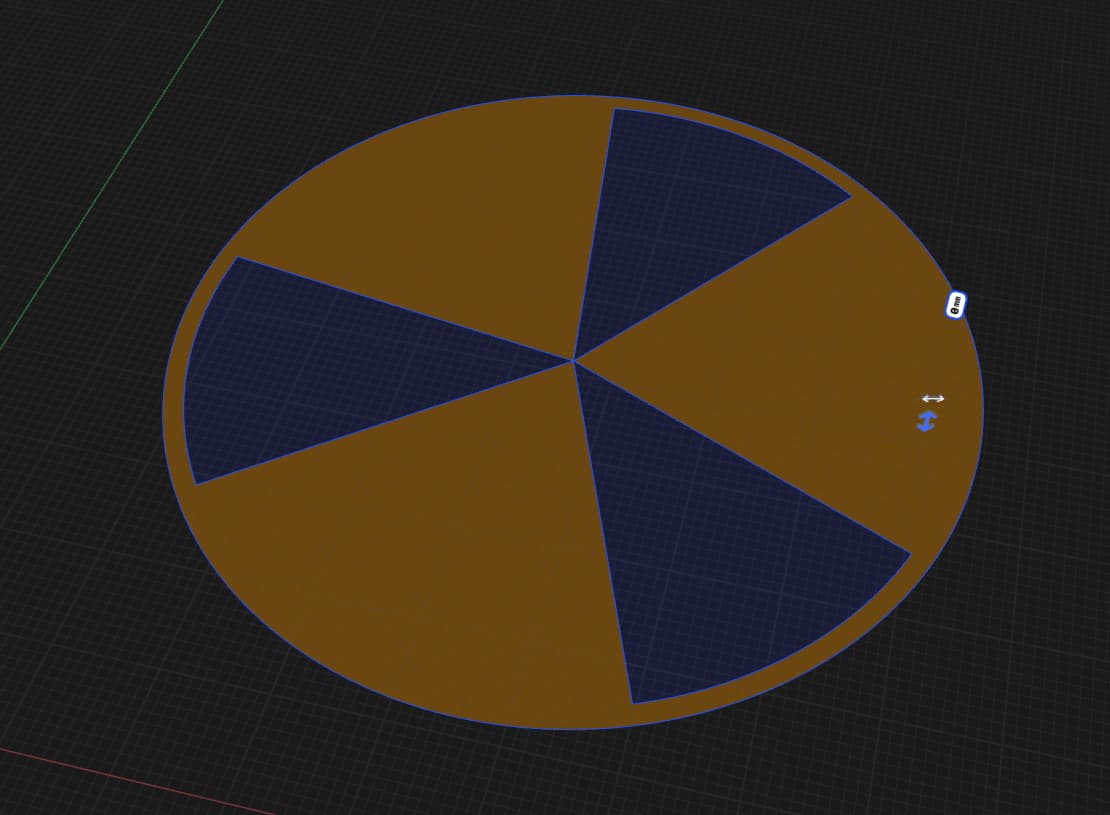
That only applies to situations where there’s actually an issue that can be fixed. For example, in the last case, there’s no problem with the spline at all — the issue is with the body you’re trying to create.
I can easily recreate the same situation without using splines. For example, this one won’t extrude for the same reason, even though it doesn’t use splines at all.
It’s always based on what the designer wants.
I was just trying to get clarification on this solution. So I though I suggest “mark felt” font as an example.
Does what you suggest apply to that Mark font? If not not?
Or are you saying each problem have different, each its own tailored individual solution?
The method of identification can be applied, but the solution should be chosen based on the specific situation.
Of course. How could it be any other way? If one solution worked for every problem, then let’s use my method to solve world hunger — starting with the children in Africa.
Ok I will try again, trying to figure out what you did.
Here is what I see and correct me if what I saw is incorrect.
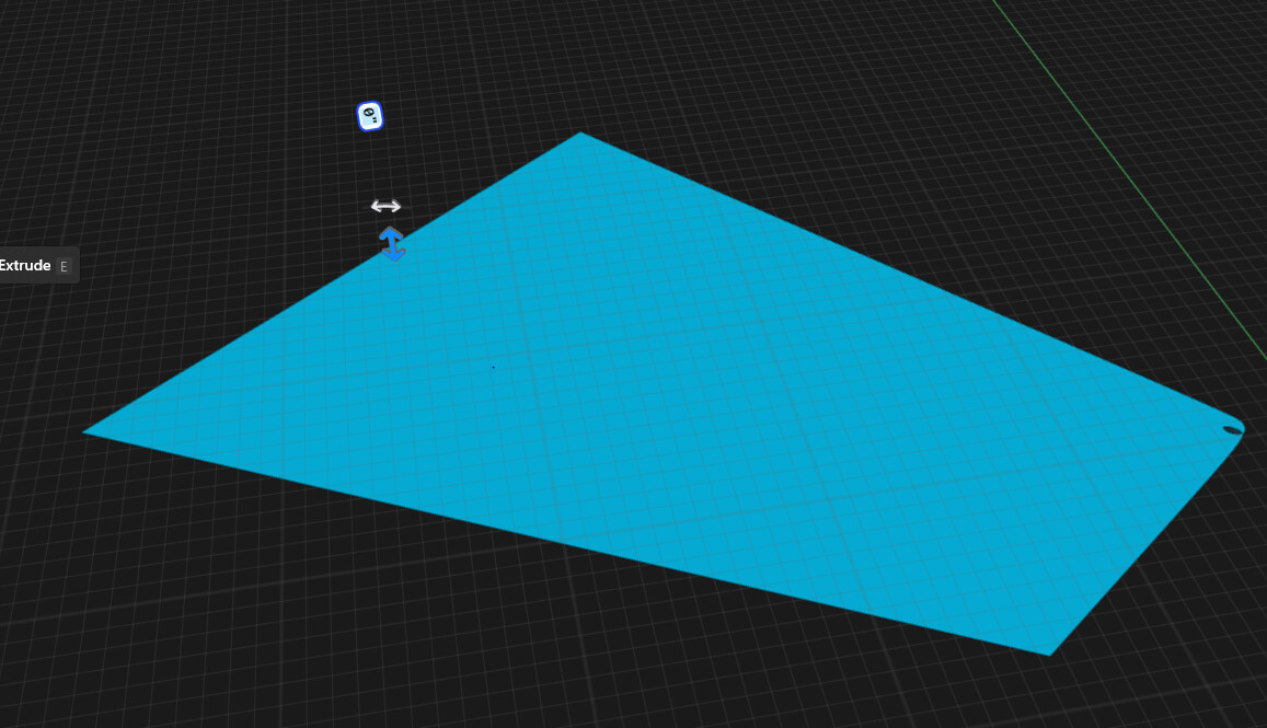
Finally Extrudes.
My Mark Felt example I took your idea applied it so I selected that dot (also in general I know ahead of time where the problem is). Deleted that dot and I was able to extrude. In Mark font we are looking for the KINK not broken sketch. My confusion, I followed your example above deleted the dotted sketch, it worked but you select another area to fix.
I suggested another example sketch that can’t be extruded, which is how the KINK is formed for most or if not all of the sketch extrusion problem, I just made it bigger so it can be seen. But that has no sharp corners, or break or that dotted control point so I wondered how to fix that.
It is basically the original problem but blown up to see what the problem is, you can convert the corners to curve but that will just make it round change to the shape and still it will not extrude, so in his cause would you delete the problem control point because there is a certain CUE you see with the control points like the dotted circle or is it big enough to see the problem so just delete the control points?
I’m tired of explaining the same things over and over again.
Maybe it’s my English level that doesn’t let me explain things clearly enough, or maybe it’s something else…
I’ve already written about each of the problems shown separately and answered all the questions that were asked.
Most likely my issue. Not understanding how to identify the problem area. But someone else will utilize it and show the example.
U know the same question will come up again by someone else guaranteed! ![]()