Can't extrude a spline sketch

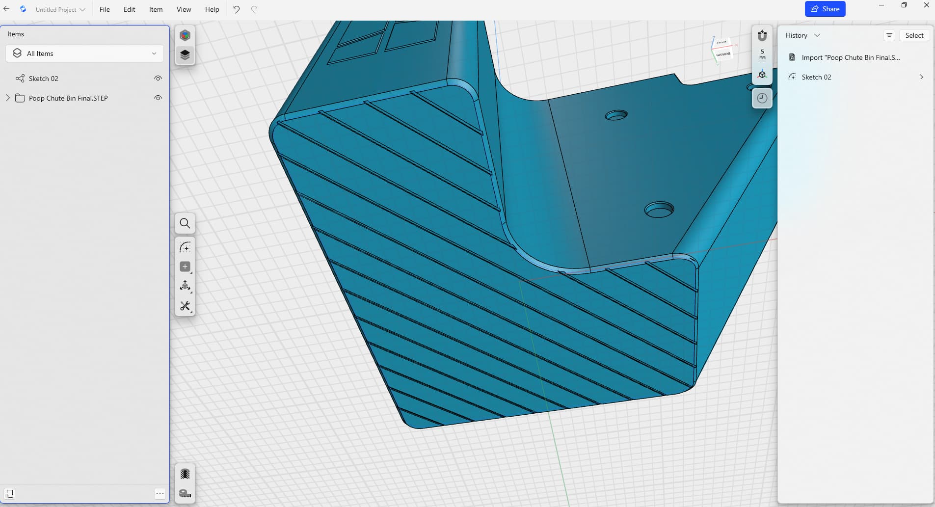
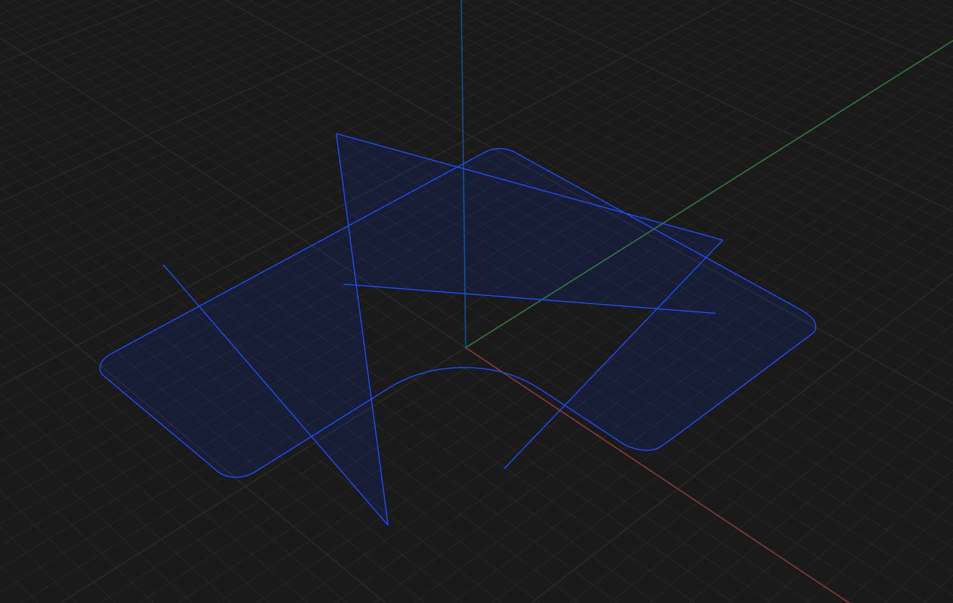
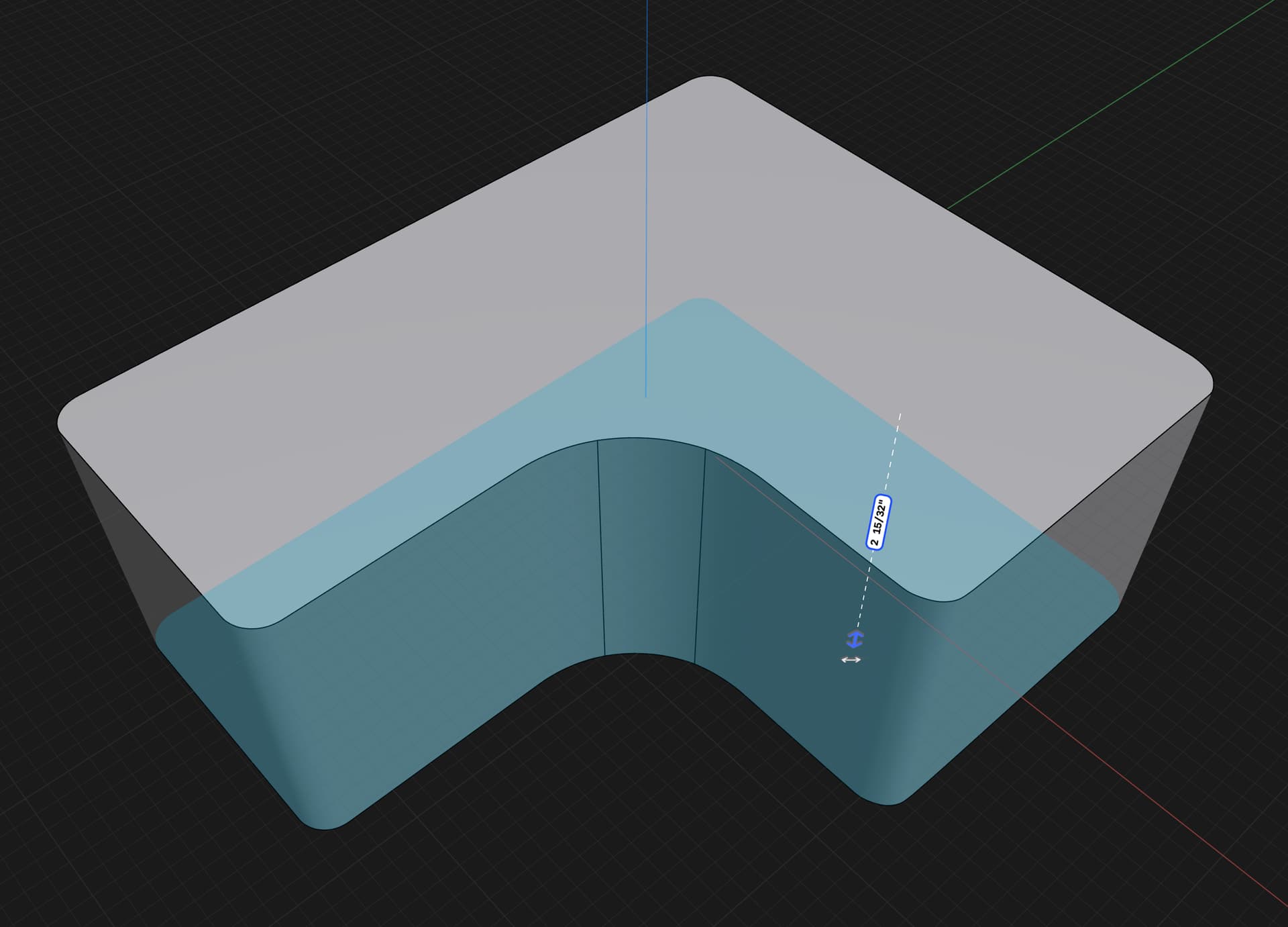
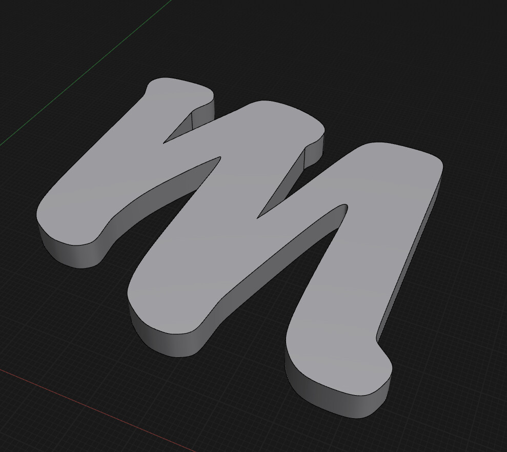
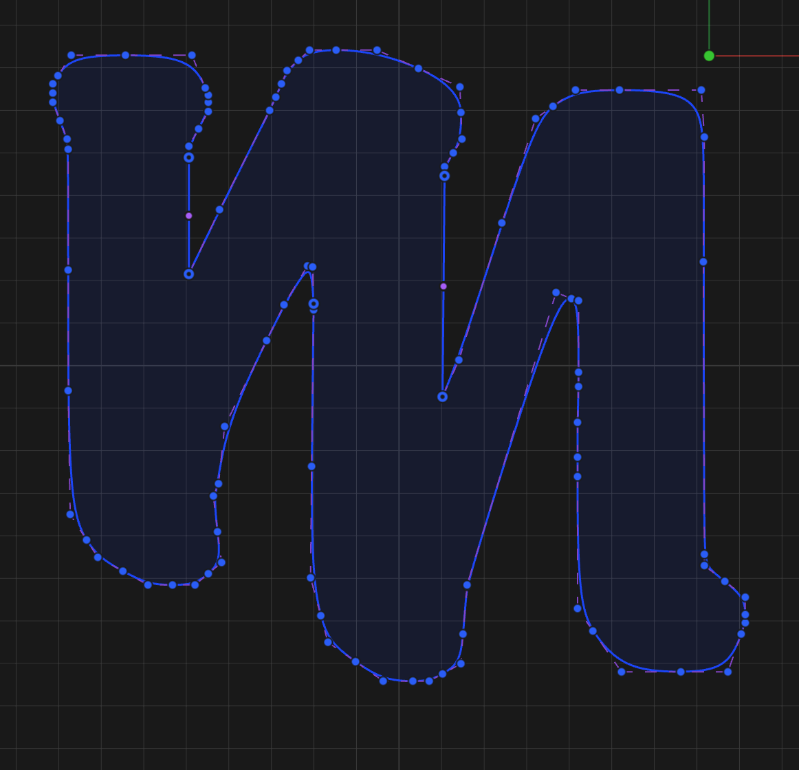
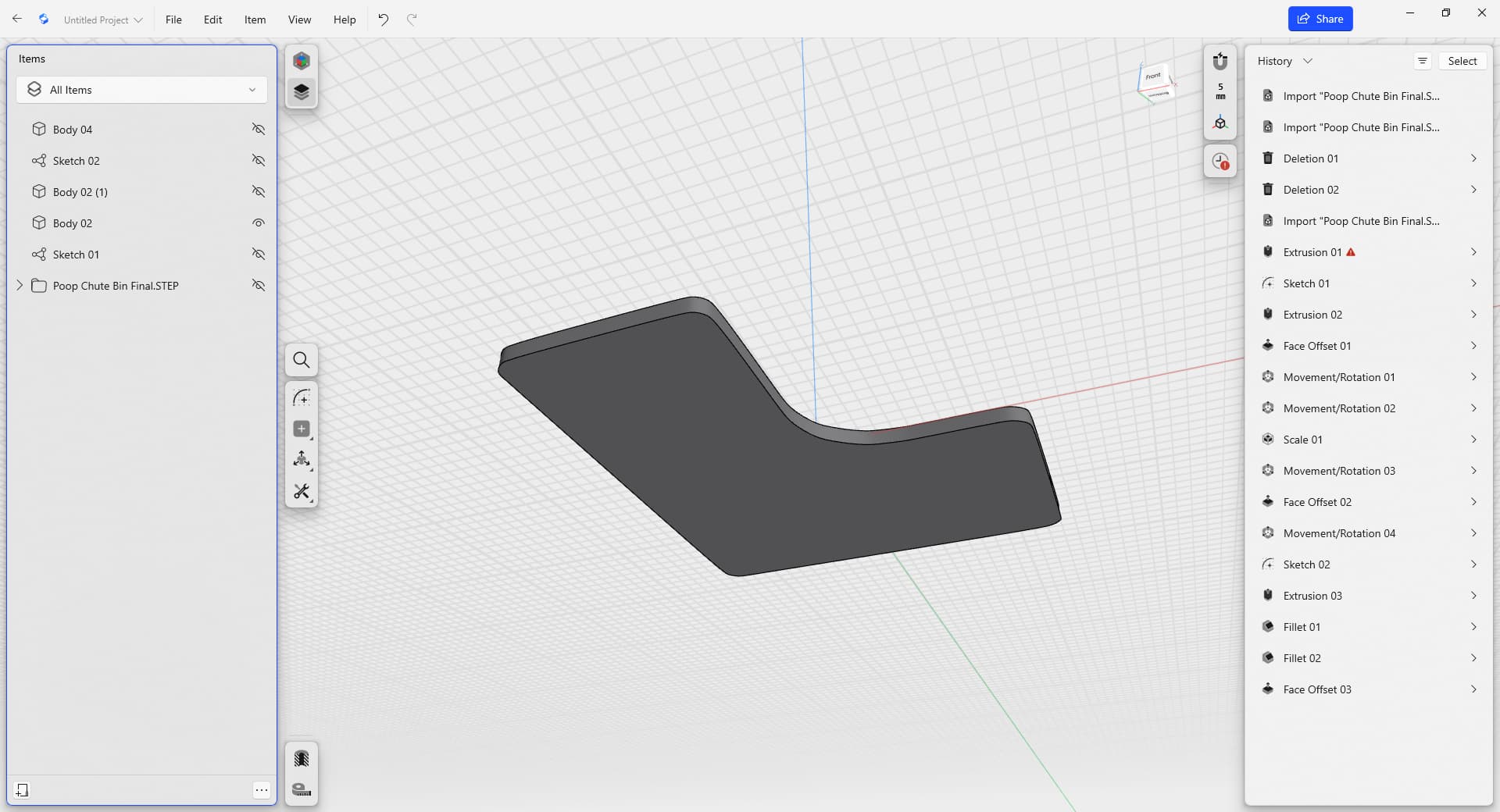
I’m attempting to create a base for an object imported as a step file. I drew a spline around the bottom of the object. I did have to go back and touch up a few places, but the outline appears to be contiguous. I can’t select it in order to extrude. I wanted to make a body 2mm thick using the spline sketch. Attached is a screen shot and the shapr file.
Thanks,
Mark

Poop Chute Bin 01.4.shapr (1.4 MB)

https://support.shapr3d.com/hc/en-us/requests/new

It looks like sketch is not closed. Investigate this area, its not fully connected.

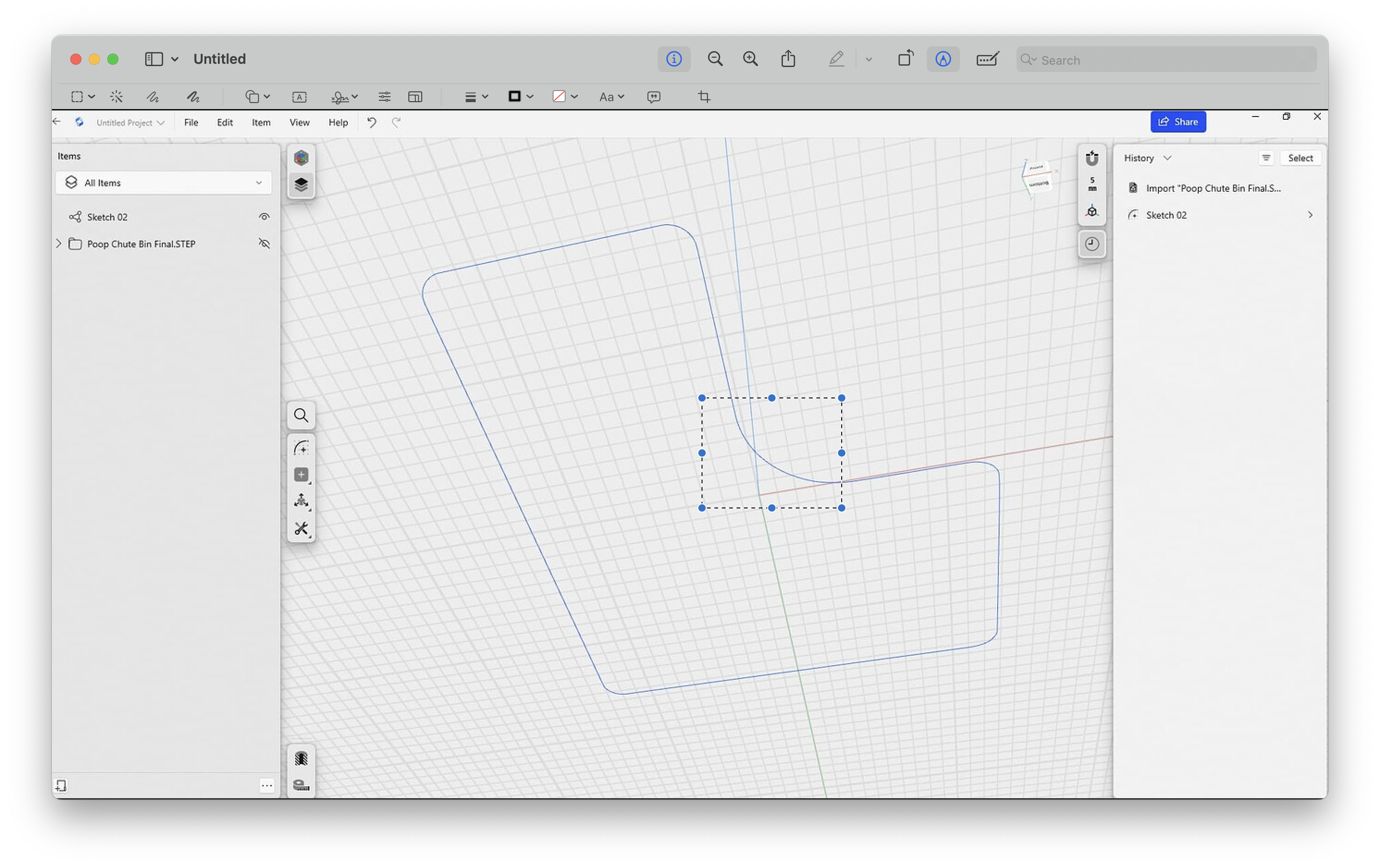
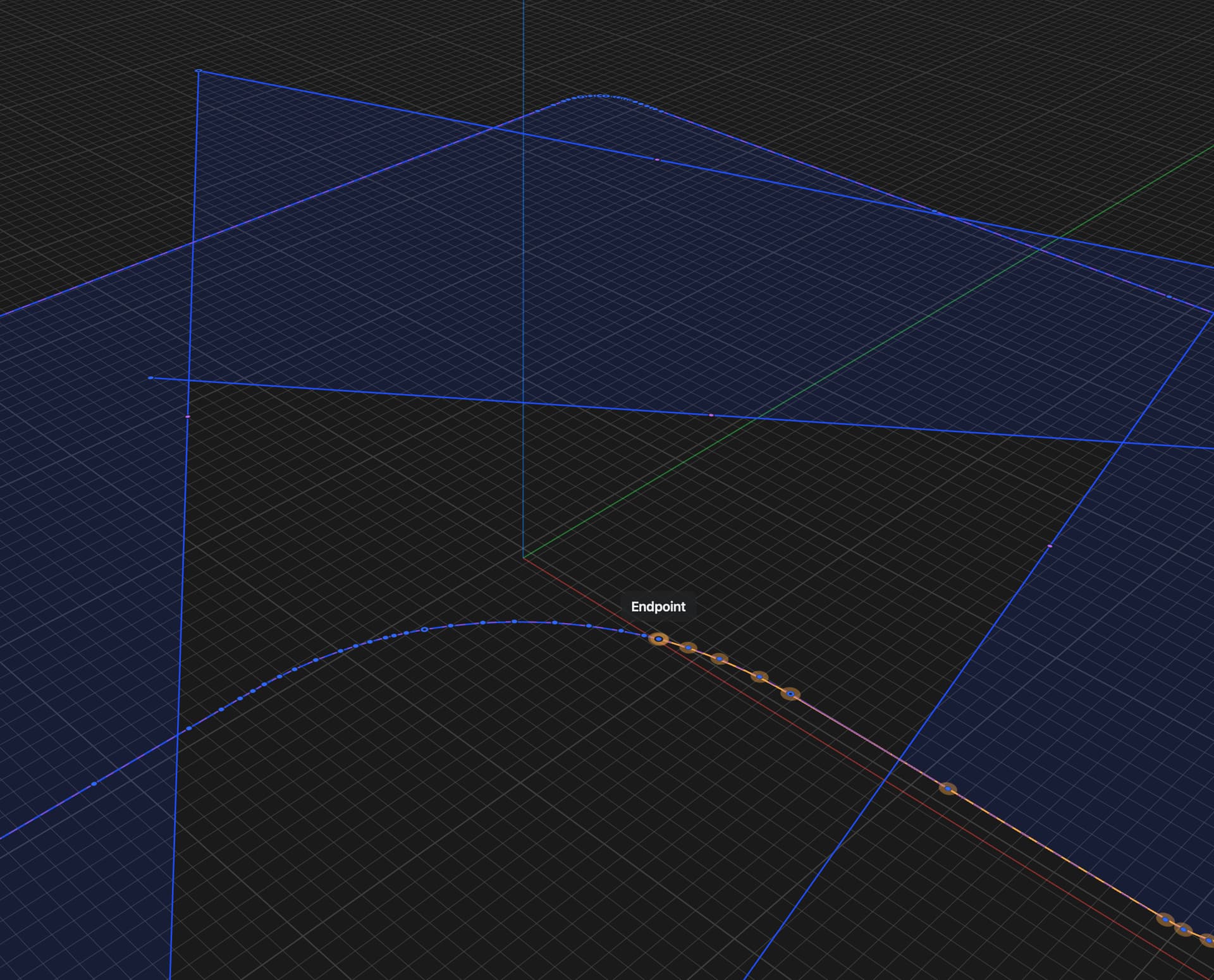
Good eyes! How in the world did you catch it? I’d gone over the circumference 3 or 4 times, but when you narrowed down this area, there it was–the smallest disconnection.

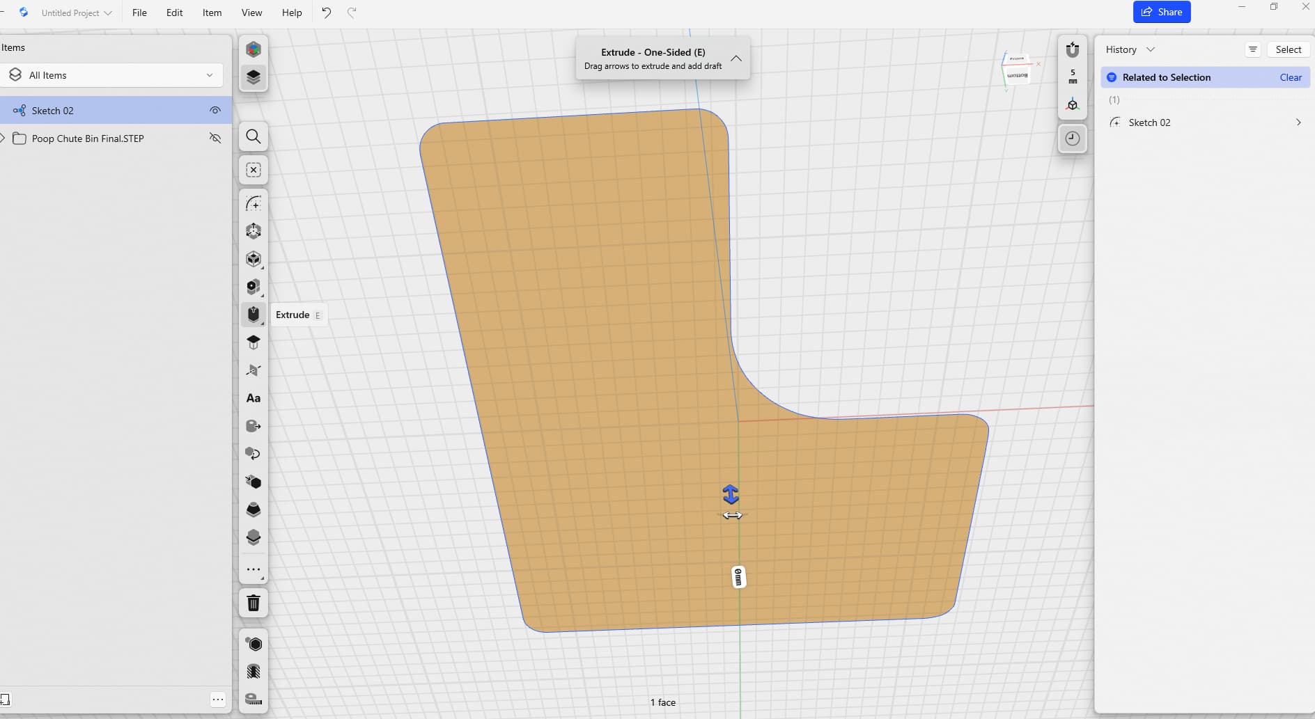
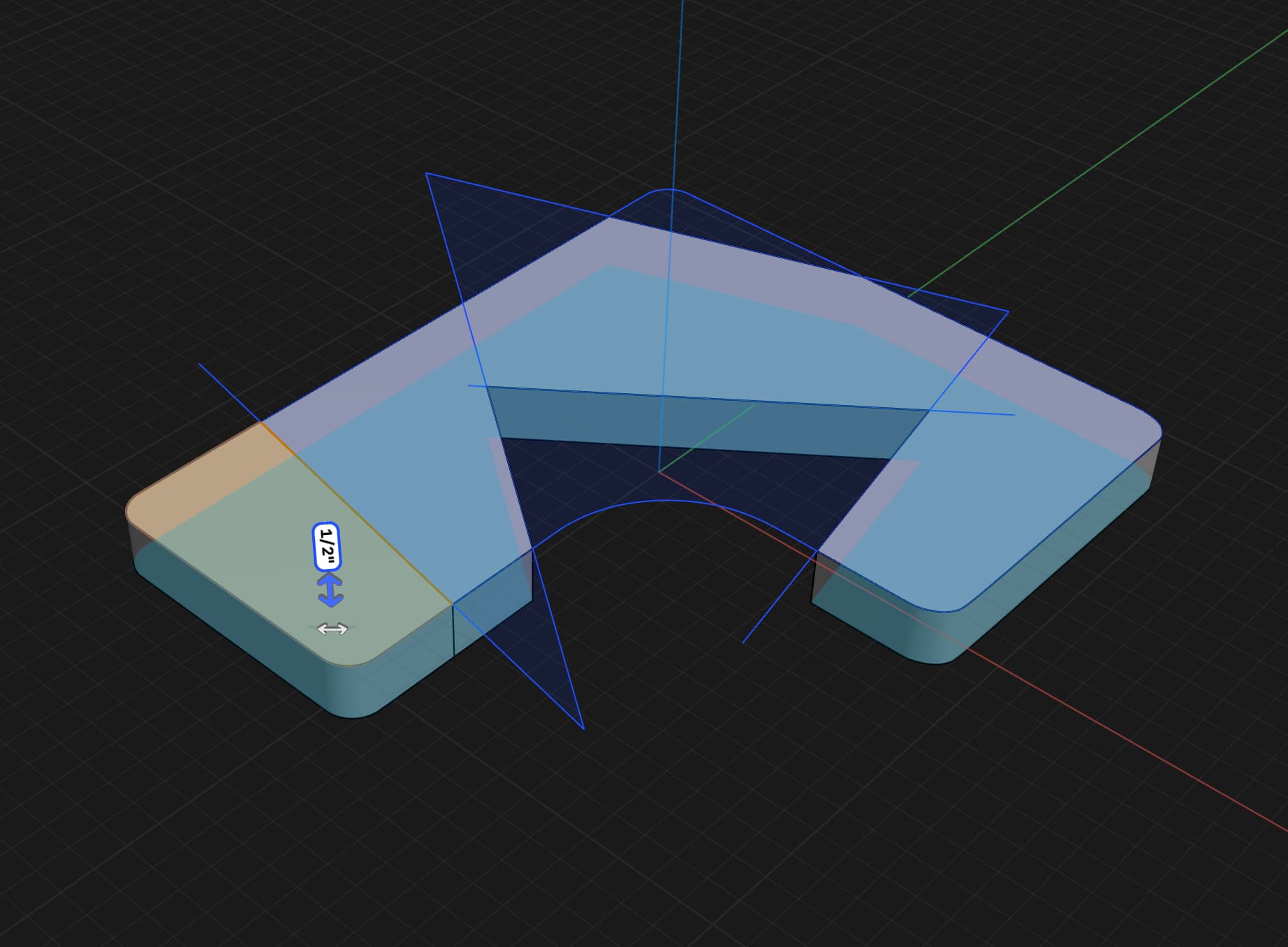
It now let’s me select the area and shows the extrusion arrows, but when I try to extrude it, I get this error message: “Face or sketch filling can’t be extruded.”

Mark


Poop Chute Bin 01.5.shapr (1.4 MB)

Here is what I did to investigate the open sketch.

Make bunch crossed lines until you can triangulate the open sketch.

Found the gap here by zooming or by selecting, moving the endpoint.

Extrude one area at time and find which section doesn’t extrude.

Since we have more issues with the sketch start moving the end points.

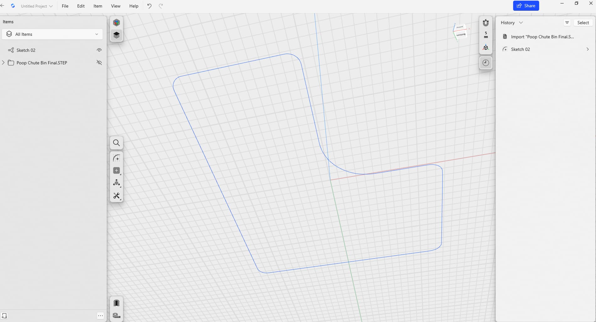
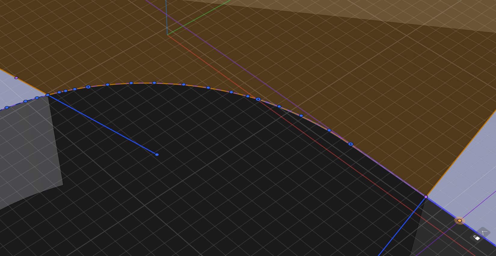
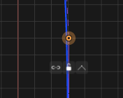
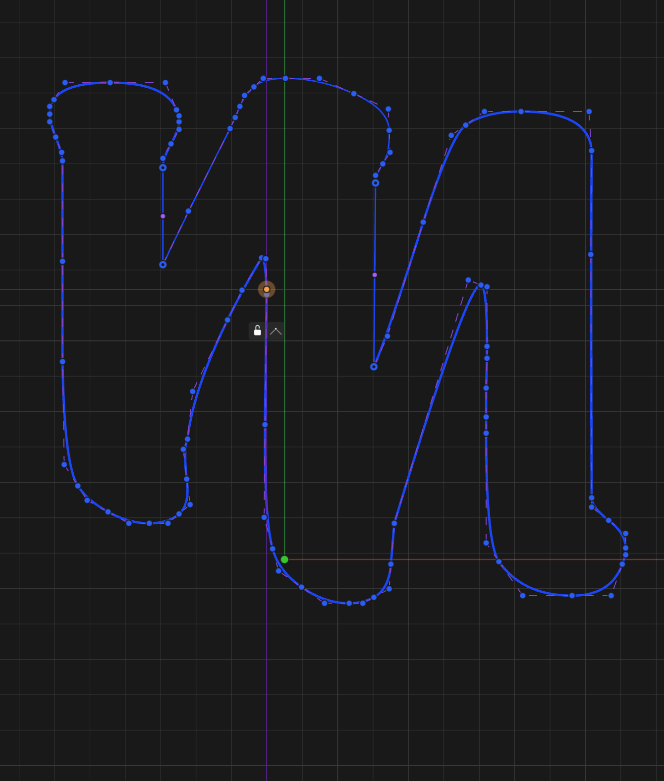
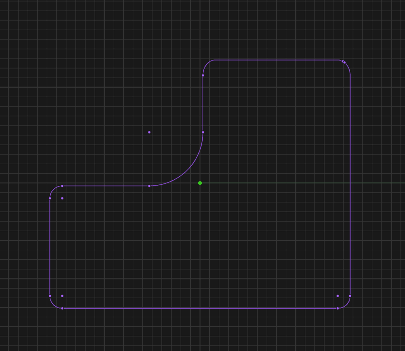
You will see at the right there is weird overlapping end points. Since I now know where the problem is undo everything, Delete that problematic endpoint on the right and you can finally extrude.


Here is a video how I found it in a seconds. (just checked the connections of all splines)

But that’s only for closing the sketch :slight_smile:

1 Like

Here is the full procedure. That’s exactly how I acted to find the issues.


Just in case someone didn’t know that, there are several visually different point in the sketches. So you can instantly understand is it connected or just sitting near each other.

On the first video I looked for unconnected point and found it very quickly.

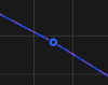
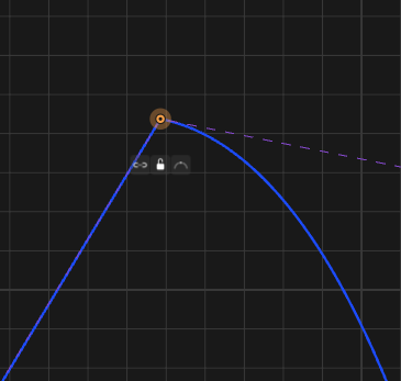
This one is connected
image

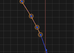
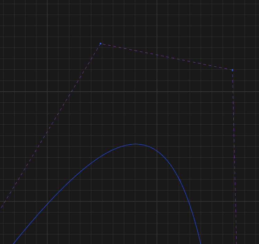
And here is very easy to understand that the points disconnected, they have different visualization.


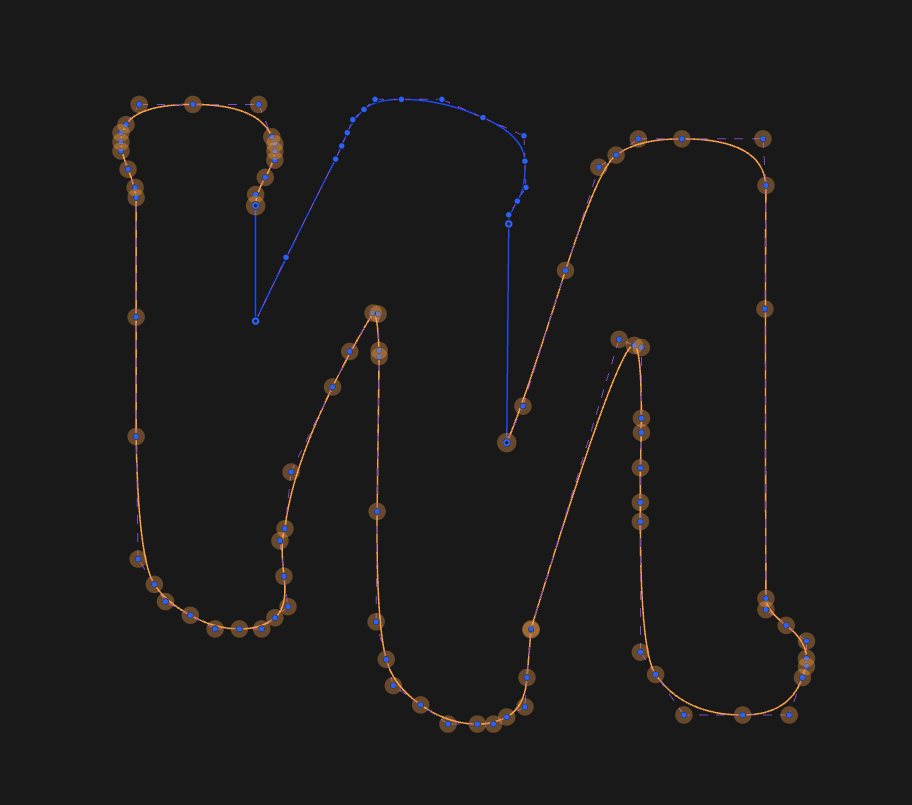
And on the second video I was looking for connection which can’t be converted to solid spline (small icon on the right tell us its already a solid spline)


That is how my brain is working :slight_smile:

2 Likes

How did you pin point thats the one that has the issue?

The point icon shows a non solid spline, but the angled icon below says it is. That’s why I instantly understand this is the problem.

Can you try it on Mark Felt font?

lower case m, its known that has a extrusion issue.

I put the problem place in the circle.

Quick fix and it is extruding without a problem

Ok I think I didn’t ask the right question, how would you identify that area has the issue.

I think the way your version works is.

Identify area point that has a hole.

And start the investigation from there.

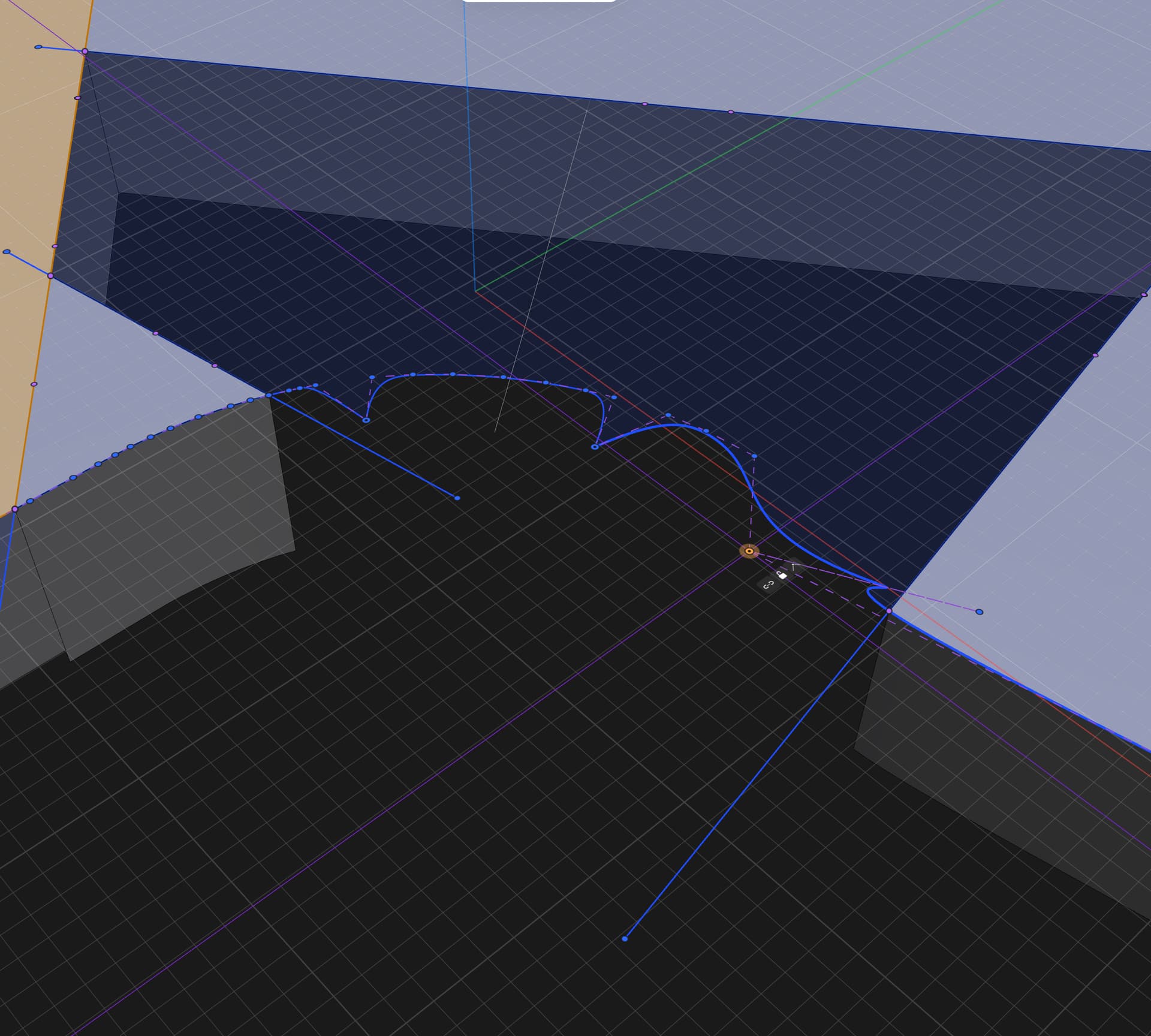
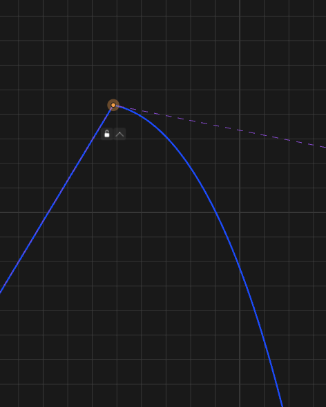
Well… The error says “can’t be extruded because it will create non-manifold body”. So I started to pay attention to sharp corners. The corners made from regular lines is ok, so I continue looking. Very quickly I noticed that this part is calculated wrong. This is a spline but it acts wrong. It shouldn’t be sharp in that state.

We see sharp corner but the icons insist it cant be sharp.

Clicking on the angled icon recalculates the spline:

After that extrusion is going ok.

1 Like

Just notice the difference. I’m not moving control points, just toggling the state.

Initial state (wrong calculate)

Changed to angled state (notice the difference in icons)

And now I return to the previous state (notice how spline is looking now)


All that just flashed in my mind in a couple of seconds :slight_smile:

So did you use the method you described earlier for this example?

For this example I just deleted this one

Yes, I’m. You variant is working also because you force recalculation by deleting control point.

I didn’t delete any. I just found the issue and fix it.


Look at this picture. We can clearly see that the selected part is a spline. But it has a sharp corner, which shouldn’t be possible for a spline.

If you toggle the control point to angled (corner) mode, it won’t be selected as a single part anymore.

So I took a closer look and noticed that the icons and the actual shape contradict each other. That’s how I realized the issue lies here.

So you describing 2 different methods?

I was trying to apply your original method to Mark Felt font, in the video you delete the control point?

I fixed it! Thanks for the tips in how to find the disconnections. This is one of first times I’ve used the spline tool. It’s a different animal for sure!

Thanks for all the help and for the discussion of various ways to troubleshoot a spline model.

Mark

The method of identification is the same.

Yes. This is the action I took to fix. Actions can be different. In that case was easier to delete one redundant control point.

The font issue and the TC issue are different, but the method of identification was the same.

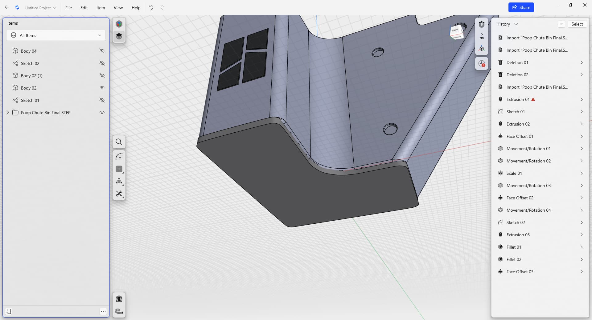
Don’t want to disappoint you but in you case no spline drawings is needed at all :slight_smile: Since the bin is imported from step file you can easily project its shape on the sketch and work with this projection.

Here is how projection is looks: