New here, just started last night, quick question about something I couldn’t find in here or in any of the tutorials I looked at, is there a simple tool for countersinking holes on a drawing?
Hi @Ford Welcome to the Forum 
Last time I created a Countersink it was somewhat different , S3D is developed at a staggering rate and some things have to change. Unless the Team can tell us otherwise?
Please bear in mind that this has been written up to explain the complete process, you obviously do not need any help creating the Hole.
This is one way to create a Countersink, in this case a 50 x 50 x 8mm thick plate has a 6mm hole with a 45º countersink:
Double tap with a finger on the surface that you need to Sketch on:

Select the Hole to be and drag through:


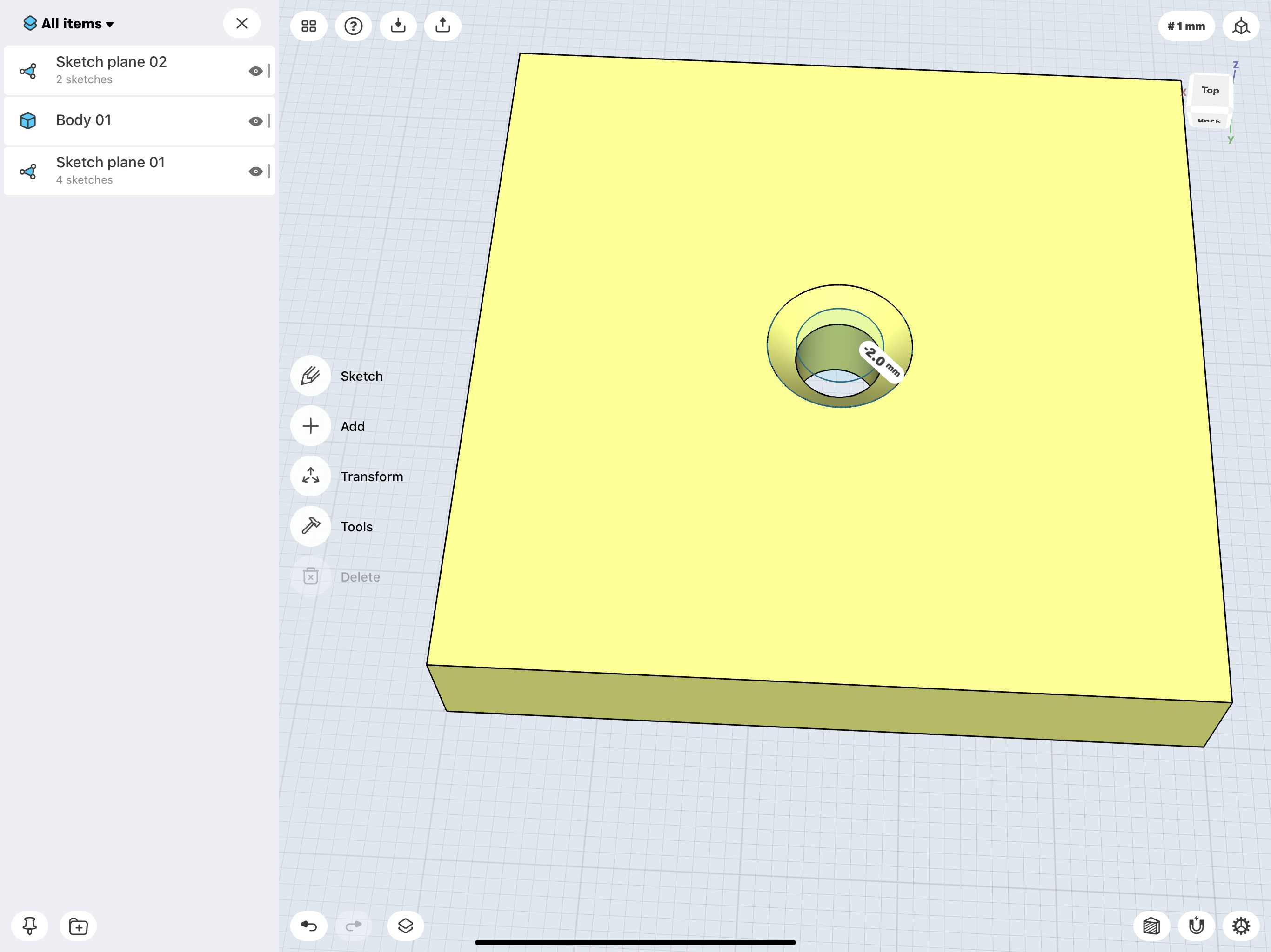
Drag the Double Arrow Outward:

Hide the Sketch plane:

Happy S3Ding
If the above Countersink result is not what you are looking for, and a specific Countersink Angle is required, it will be necessary to adopt a different approach. The following offers one MO, as at 29 February 2020.
The following Link may be useful:
https://en.wikipedia.org/wiki/Countersink
The Combined Angle, of the Example in the Post above, i.e., 45º, is 90º.
Countersink Angles vary dependent upon the System in use, e.g., ISO Metric Standard being 89.9º, or 44.95º for the Countersink Forming Shape.
If that level of precision is not essential any Even Numbered Angle between 60º and 120º could be used, being conveniently divisible by 2.
Other considerations may be advisable to accommodate Countersink Heads with Socket Drives, where it may be best to deploy shallow angles, that can handle deeper Sockets without recourse to ungainly Head Diameters? A common real life problem being inadequate shallow Sockets that are easily stripped by less than very careful operatives.
Select an appropriate Surface for a Construction Plane [CP]:
Use Add > CP > Offset to the Centre Point of the Hole:


Make use of the Section View Tool, found at Lower Right, for placement of the Countersink Forming Shape. Use of a Guide Line for the Countersink Maximum Diameter is optional:
Add > Construction Axis or Substitute Line [this being used in this case]:


Sketch onto this CP the Countersink Forming Shape, in the appropriate position:
Transform > Move/Copy > in conjunction with the + Badge [useful to create precise Angle(s)]

Move the Shape downward to coincide with the Maximum Diameter Guide Line:
Then use Tools > Revolve to form the Countersink:

Next use Tools > Subtract to remove the Countersink Body:
Lastly Hide the relevant Sketch plane(s):

