First of all,
I love Shapr3D. Ive worked in a lot of different CAD-programs throughout my life, and even though there is a lot of things that are yet not in place I prefer using Shapr because of the simplicity of the interface and that iPad app lets me work wherever I am. With that said, I still struggle with the technical drawing part of the application. As for now I export my technical drawings from Shapr to PDF and import them to InDesign (Adobe) to make it work. This is not an ideal workflow.
I’ve attached images of how I want my 2D drawing to look like.


hkGbT7hqyR3OgDgf6g19ZvGgzja.jpeg)

Suggestions of improvements:
Bill of material
I’ve seen in the community this have been adressed before. No need to elaborate on this.
One document
This have also been adressed before. I want my technical drawing, including several pages, to be printable in one document. As for now I have to manually make all the drawings to one PDF.
Boarder without numbers
I want to have the option to have a boarder but with or without numbers/ABC.
Titel block
I want more freedom och making this layout suitable for me, my company or my client.
I want to be able to choose how many rows, how many columns and how to separate the columns.
Saved presets
As for now I redo the Title block for every single drawing. This is very time consuming.
I either want to make a present I can import for specific projects or at least have the same info saved in the title block when making a new drawing in the same project.
This includes the presets for line weight etc.
Line weight
As for now I experience that line weight, dimensions, text etc is some what clumsy/chubby.
The acceptable line weights (in mm) that can be used in a drawing are as follows:
0.18 | 0.25 | 0.35 | 0.5 | 0.7 | 1.0 | 1.4 | 2.0 |
Native for visible outline in Shapr is 0.40 when it should be 0.35 for A2, A3, A4.
Or am I missing something?
Font size
I also would like to have more option in font size.
Have just one font option i can live with.
Dimension position
I want more choices of how to position the dimension.
As for now the dimension is always on the left side on a vertical line. If I have the dimension on the right side of the object I want to have the dimension numbers on the right side of the dimension line. This is impossible now. But I would also like to have the possibility to have a vertical line dimension horizontally displayed in the middle of the line.
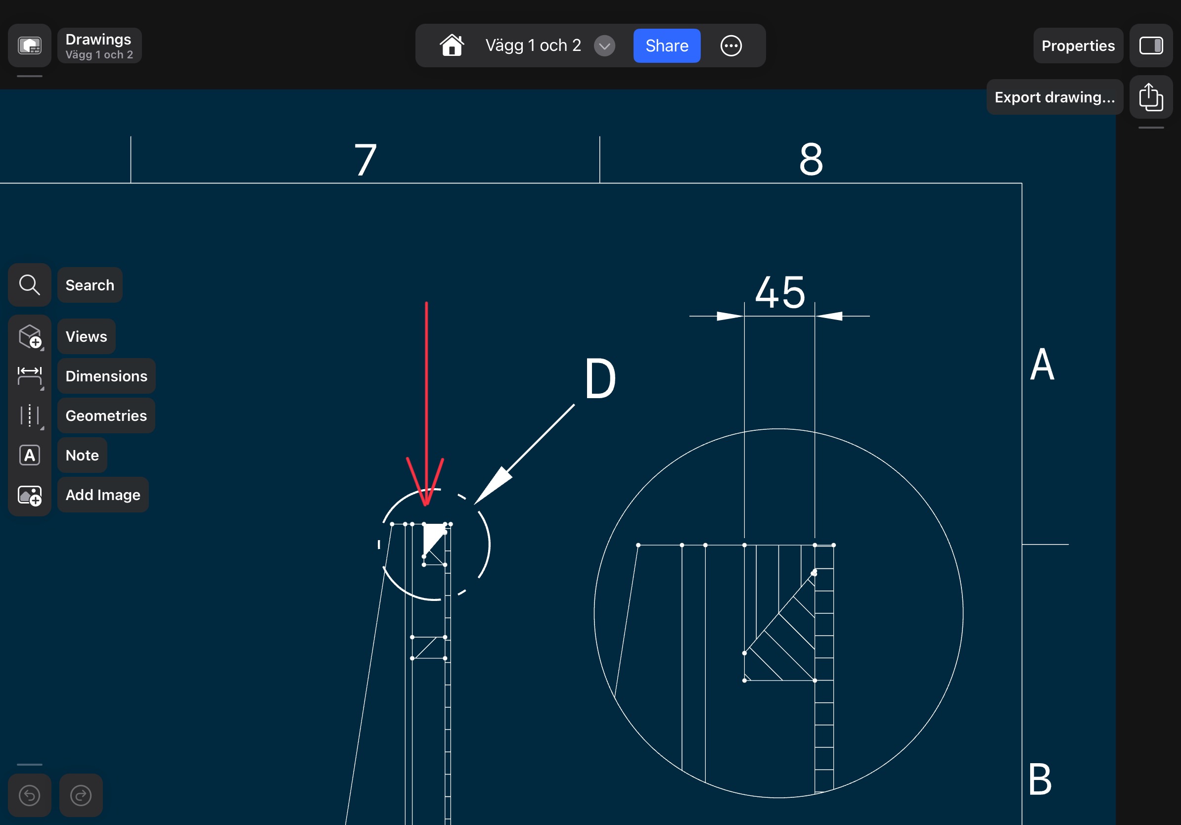
Position of Detail view
I want more freedom of choosing where the arrow highlighting the detail is positioned.
As for now it is locked to the upper right of the detail, which can be problematic in a very detailed drawing.
Also, why am I constrained to scale 1:1 as maximum size of a detail? I need some times that the detail is 2:1, 5:1 etc.
Hatches
I suspect you are aware of the problem and that it is on the road map to update this but as for now this is not professionally acceptable. Its very convenient with the automated hatching och the section views, but its very buggy. Some times a section is totally filled making it very hard to understand.
The hatches must be adjustable 360 degrees manually so it can clearly separate different parts of the drawing.
The hatches must be adjustable in how narrow or wide it is between the lines.
I can live with only one hatch type (lines) but over time i think it can be good to extend so we can illustrate different materials.
Auxiliary views
Auxiliary views is an orthographic view that is projected into any plane other than one of the six primary views. These views are typically used when an object contains some sort of inclined plane. Using the auxiliary view allows for that inclined plane (and any other significant features) to be projected in their true size and shape. More complex objects need an auxiliary view for getting the dimensioning right or for communication.
As for now it is possible to work around the the problem with making a separate drawing for this, but should be included in some way. My suggestion i to make it possible to use a plane as a primary view.
Exploded-view drawing
I want to be able to make Exploded-view drawing for communication.
As for now I can’t a sufficient one in drawing mode as the views are very constrained.
I would like this no to be Isometric, but perspective. For the moment i export a rendering from ”visualisation” but would like this to look like all the other drawing, meaning showing just drawing outlines, no texture/color/gray etc.
Named views
In a technical drawing all views should by the book be named, Font view, right view, top view etc.
Its possible to do that now but very time consuming. Preferably this should be changeable to my language manually.
Final thoughts
Wow, this became a long text! Hope I’m not ranting and that it can be to some help. Keep up to good work, Im always eager when there is a new update in your great application. I am sure is the leading CAD program in a few years!