How to make a split mould from a solid object , I have 3d scanned a drone propeller , I find very difficult to split the prop into two half , any way to do it ?

Here’s a way that might work. Early in the video I briefly show the orange mold-half just to show how the prop would create an undercut situation if you were to simply subtract the prop from the mold half.
Create a plane above the prop and Project all surfaces that can be seen normal to the plane. Extrude a New body downward and beyond the prop, then Subtract the prop and delete the bottom. The prop + extruded body can now be subtracted from the mold. Do the same for the upper mold.
-Mike
Wonderful, thanks a lot , I will try them now

Delete all the interior lines and leave only the perimeter. Then try using Extrude.
-Mike
Well the good news is that you only really need to mold one of the blades to the center hole, then rotate a copy of the two mold halves 180 degrees and union the top halves and bottom halves to each other.
The problem is that a vertical plug into a block is not how you want to split such a mold.
How did you model the prop in the first place?
It should have involved splines. If so there is a spline that defines the very leading edge of the blade and another spline the defines the very trailing edge of the blade. None of the other splines are needed except maybe the central hole.
The separation line between the mold halves will have to have the contours of these splines, if you viewed the model in its plane of rotation.
So first project edges from the prop to a vertical plane between the two props.
As you point out, this will be a forest of splines… but you carefully delete every spline except for the splines that follow the centerline of the prop blade along the leading edge and the trailing edge. These two main splines define the contour of the separation plane that will match the leading and trailing edges of the prop in its flattest dimension.
Call this the separation view.
You will want to do the same projection trick to the x/y plane below the prop- deleting all but the splines that define One blade’s leading and trailing edge- these should be easy to identify in x/y as the outermost lines of the projection.
Call this the cavity view.
Look at the ‘separation’ view and identify the spline that forms the leading edge of the prop.
This is the higher, and flatter line in the separation plane projection. You only need half the prop- so bisect the spline at the centerpoint and delete the other half. Connect the cut end to the other end by drawing the other three sides of a box generous enough to encompass the entire half prop with room to spare to form the bottom half of the mold. The top line of this profile should be the edgewise projection of the prop’s upper, leading edge.
Extrude this profile till the new body runs past the trailing edge of the half of the prop you are molding. What you should see is a block that’s runs thru the prop and conceals everything except a tiny sliver of the prop blade that sticks up above the block exactly at the leading edge.
At the hub, you should see a slice of the top of the flat area at the hub.
Now go to the Cavity view projection on the x/y plane under the prop. Delete every spline except for the spline defining the trailing edge of the prop blade, all the way to the hub. Add lines to this spline to create a profile that has the trailing edge on one side, and creates a box big enough to encompass the portion of the first extrusion that ran beyond the trailing edge. What you are looking to do is extrude a Vertical body perpendicular to the first extrusion that will cut off the first extrusion right at the very trailing edge. ( you also want to cut the Hole spline at the hub out, as well )
Now subtract the prop from the first extrusion. This should leave two parts. The main block under the prop with the leading edge separation plane. And a thin sliver of material isolated from the rest of the block when you cut the prop out. Delete this sliver of material.
Now go back to the separation plane view- You want to take the OTHER spline, that defines the trailing edge of the prop blade and complete its profile so you can extrude the same length block- but using this spline that runs lower.
Extrude this block well past the trailing edge of the prop to create the separation plane on the trailing edge side of the blade.
Now subtract the prop from this extrusion.
When you turn off the prop, you should see a cavity shaped like the negative of the prop blade composed of the two extrusions.
Union them, and rotate a copy of this object 180 degrees around the z axis.
Union that second half to the first to form the lower mold half.
Select the bottom face of that block and extrude a new body running vertically up past the separation plane of the existing mold half. Subtract lower mold half from this third extrusion. And then subtract the prop from this third extrusion.
You should now have a mold of the upper and lower half of the prop, cleanly parted at the widest part of the blades along their entire length.
I think it it canot draw the props splitted mould in the S3D ( I hope not for long)
The problems are:
The mid line of the leading edge is a 3d spline.
The trailing edge vertical side is a twisted surface
if the split plane does not fit the centerlines, an undercut is created, at the leading edge.
Hi there,
All valid points. Note that the author has a 3D scan to start with. He is not creating the prop. He is asking how to spit it. My solution works however it is not ideal for a true mold. The correct parting line of the mold would be curved or sloped according to contours of the prop at the perimeter. A vertical projection of the part perimeter would dictate where the mold splits regardless of centerlines, meaning no undercuts.
-Mike
Scan data would be STL- This prop has been surfaced in some app or modeled in Solidworks or some other procedural modeler. What I posted was just a variation on your post, that would use an edgewise projection to capture the actual spline at the leading and trailing edges so that you could extrude the curving surface needed for a proper parting line.
Here’s another way of making a better result. To show pictures of this, I had to model a prop in Shapr, since I don’t have the model you’re dealing with…
But its doable with the prop you have as long as you can make copies of the prop and slice the prop at regular intervals to obtain the cross section of the prop at various points.
To start, I drew a bunch of planes with various profiles of the prop airfoil that define the change in size and angle of attack.

I lofted the prop in 3 sections, the root where the shape changes the most dramatically, the long part of the blade where it tapers smoothly, and the slightly rounded tip- this gave me a better result than trying to loft all the profiles in one go.
Then I unioned them into a solid blade.

Here you can see that I separately modeled the hub… drafted in both direction ( even the hole in the center has a reverse draft of 1 degree ). Note how carefully laying out the first profile for the blade with points on the xy plane allows me to align the separation plane of the hub with the separation plane of the blade.
Then I edited each blade profile sketch to add a profile of the mold block. In the background you can see the root profile with its flat separation plane. And you can see how the leading edge of the blade is higher than that and the trailing edge of the blade is lower- I draw a horizontal line from the edge of the blade in both directions, and link them into a closed profile of the mold block that matches the width and bottom line of the root block.


I then draw a straight line segment inside the profile of the blade airfoil- essentially defining the Chord of the airfoil. This will result in the mold block I eventually loft crossing the surface of the blade to its midpoint.

I then deleted all the airfoil profiles from each sketch… and note I added one additional sketch plane that was a copy of the plane at the very tip- so the mold will run past the end of the prop.

Its important that I use the same planes I lofted the prop with… and loft the mold body in the same sections I did the Prop.

Then I turn on the prop body and examine how well the mold line follows the edge of the prop.

As you can see, i have a perfect match everywhere except at the root section of the prop where the shape changes the most across only two profiles… the solution is simple, I am going to re-loft this separate section of the mold after I add several more profiles to guide the steep transition of the separation plane.

To get them right, I made a copy of the prop blade, and cut it off at each new plane to redraw the Chord line and the horizontal separation lines in correct alignment.
Then I re-lofted this mold section.
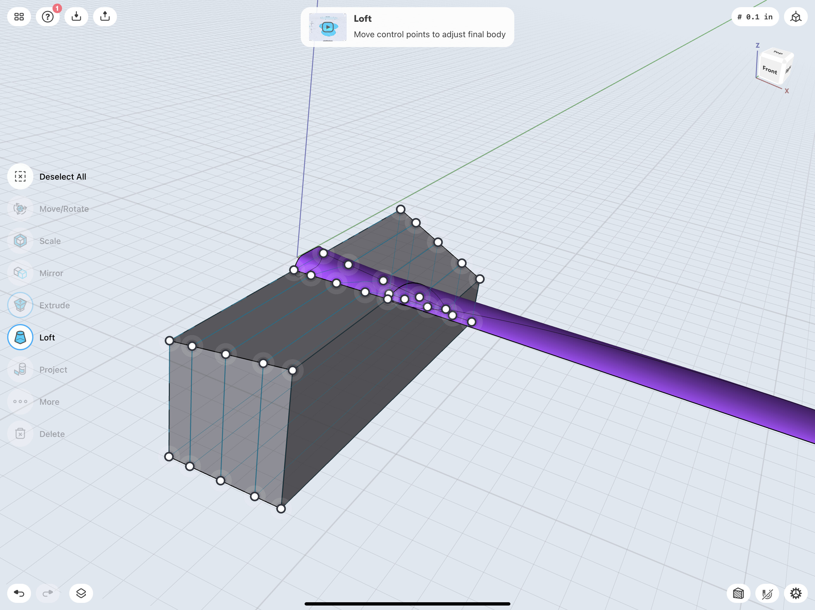

The final result looked perfect, so I unioned all the separate lofts into single body and used rotate around axis to make a copy of the mold block at 180 degrees-
I used the extrude tool on the bottom face of the block to create a solid upper mold block body… and I moved the resulting block up a few mm just so i could easily select the lower mold half.
Then I subtracted the lower mold half from the block- creating an upper and lower mold half with a mating separation line.

After that, I just subtracted the prop from each mold half to create the cavity.


Next would be determining gates and sprues, adding any registration keys or pins…
To do this with your existing prop- just create a copy of the prop and create a sketch of the basic mold block at the centerline of the prop. Add to this a big rectangle that surrounds the end view of the prop.
Then slide off as many copies of the sketch and arrange them along the blade- put more, closer together where the blade changes shape dramatically, they can be fewer and farther apart where the change is more gradual.
Then use the rectangle profile on each plane to cut off the end of the prop so you can then sketch on the plane the horizontal separation lines and the chord line thru the center of the prop’s airfoil at each cross section.
Well said. Great detail too!
I noticed on you Bio that back in the day you beta tested what would be Photoshop.
Do you remember The Art Department for the Amiga? (Loaders, Savers, and Operators)
-Mike
I never had an amiga… My first computer was the Mac SE - with the tiny little two color screen ( grays were dithered )- but back when PCs were all orange or green text on a black CRT tube, the Mac at least could do art.
I cut my teeth on superpaint, illustrator and pagemaker, which were only available on the Mac at the time.
I ended up a beta tester for the company that made superpaint… because I figured out a way to use their software to get a seven color apple imagewriter II printer to produce about 120,000 different colors, and they were local.
They developed an app called Digital Darkroom that was essentially a grayscale only photo editor. As beta tester i was promised the final product when they released it, But then they disappeared. Closed shop.
About a 6 months later I got a free copy of Photoshop in the mail… Adobe had bought out Silicon Graphics just to get their hands on Digital Darkroom. They Effectively just tripled the code to run the same software, but for Red, Green and Blue, rather than just gray. So that’s how I ended up with Photoshop without having to pay for it.
But then, I was doing sculpting, moldmaking, and product development for a long time before I had a computer… and the computer really didn’t start to impact the physical molding, modeling and development world until about ten years on from my first computer.
I used to point up large statues the way Michelangelo did.
Today, I scan the maquette and have it CNC milled in urethane foam on a 7 axis robot.
Wonderful that’s great detail
Shall I share the. X T for better understanding