I want merge and cut/subtract parts from a mesh .obj or .stl
I want to cut out the middle part and simple make the one on the left bigger.

Download .shapr file
Hi @ElT Welcome to the Forum.
Item on Left:
It depends how you want to enlarge this item
Transform > Scale [available also in the Smart Menu on the side] was used in this case:
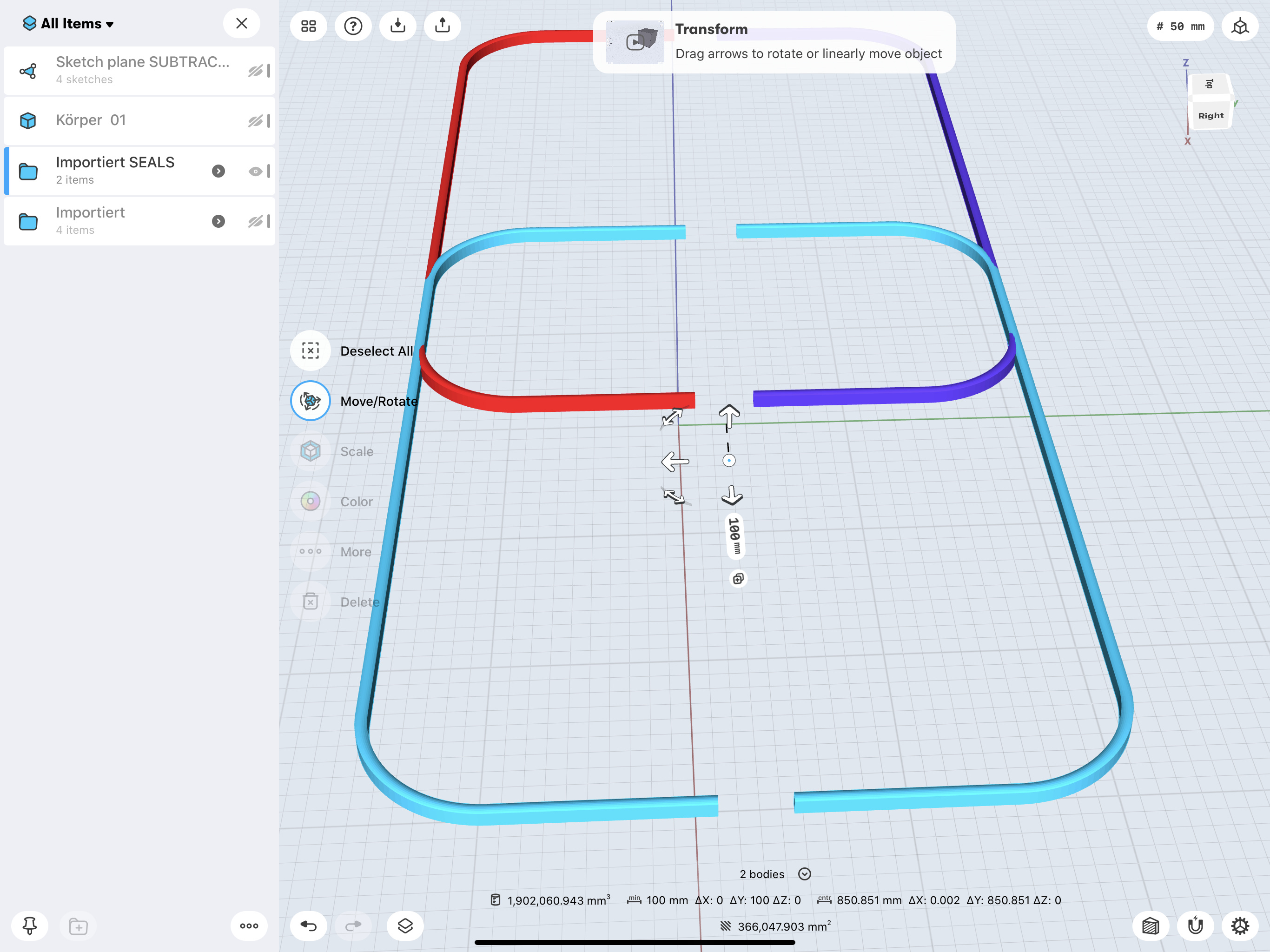
Items on the right:
More information would be needed to give further advice but the individual parts can be Selected.
In this case one part has been moved to the right using Transform > Move/Rotate
If you need more help just shout.
Happy S3Ding.
Thank for your fast response 
But scaling changes also the thickness.
I want to make a Vakuum box and this will be the rubber sealing ring, so the thickness must stay the same.
I tried to copy/rearrange them and just cutting out the middle, to have a stretched version with same thickness.
In this screen shot you can see the box, i have rearranged 4 of those to get the right „dimensions“. Now i want to merge all 4, and then cut from the new object along the yellow lines, i want the redlines to despair/subtract, and the blue lines indicates what i want to keep.
Hi, how about we just create a new solid body rubber sealing within the app which then be easily resized and edited.
I used the mesh object as a reference to make a sketch of the sealing ring from where a extruded the solid body.
Attached is the workspace with the new body and you can simply resize, position, and make adjustments to the new solid body( no more mesh editing limitations).
I hope that this helps fix44.shapr (1.7 MB)
Hmm, first really nice of you and thank you for trying to sketch it :))
But I didn‘t want to sketch from new because it had a defined height and slight taper angel. I don‘t have measurements, so that’s the reason why I am patch working around with the original mesh.
Is there maybe a way to convert the mesh to something more adjustable? 
Okay I see what you mean
If the object is in STL format you can try converting it to STEP format using FreeCad: https://grabcad.com/tutorials/how-to-convert-stl-to-step-using-freecad
Then import the STEP file into the app as this better edited.
@ElT
It is possibly much easier to do what is needed working within S3D rather than importing.
If you know, or can measure the dimensions/radii of the corner arcs/curves and define the profile of the ‘seal/gasket’, then the following will be easy.
Use Sketch > Rectangle to create the centre line of the ‘seal/gasket’
Still in Sketch, if appropriate use Circle to create the corners, then use Trim to remove unwanted Lines, including the three remaining:
Next use Add > Construction Plane > choose option Perpendicular to Curve at Point
Tap on the Plane created using a Finger then Sketch the Profile/Cross Section of the ‘seal/gasket’ centred on the centre line already created, When the Profile is completed Hide the Plane using the Items feature to the left [Tap on the rightmost Icon in the bottom left Menu]:
Then, see above, use Tools > Sweep to form the ‘seal/gasket’, tap on the next line until it is completed:
Then hide the Sketch Planes to reveal just the ‘seal/gasket’.
@Victor_Shapr3D
I have now tried to convert it to step, it worked kinda but the proportion got lost fully.
@Gelphyn
Thank you for your detailed explanation this looks clean, but how can i measure the dimensions/radii from a mesh object?
The problem is that I don‘t have any values to calculate with.
@ElT
Having converted from SketchUp Make v8 [last Free and useful copy] I work only with S3D.
Because I am not completely familiar with manipulating STEP Files I do not have an answer to your question, if indeed it is possible. Also please accept that this is written for the wider Community.
However prior to:
Anticipating a possible upcoming question ![]() , I had found that it was possible to cut the ‘seals/gaskets’ using a Cuboid Body therefore it would be possible, by using copies, to reconstruct the desired ‘seal/gasket’.
, I had found that it was possible to cut the ‘seals/gaskets’ using a Cuboid Body therefore it would be possible, by using copies, to reconstruct the desired ‘seal/gasket’.
The following is only one method of achieving the objective.
Using the Closed Shape below the ‘seals/gaskets’ create a Construction Plane choosing the Offset option, and drag the Double Arrow upward to, say, 2,000mm. Then Hide everything other than the needed ‘seals/gaskets’, Select all visible ‘seals/gaskets’ and click on the Add Folder Icon [At bottom of Items] Name this Folder [Originals in this case] to make future selection easier:
NB. It is a good idea ![]() at this stage make a Duplicate of this Design and make further Duplicates at every significant stage thereafter. Tools > Subtract can frustrate during first use.
at this stage make a Duplicate of this Design and make further Duplicates at every significant stage thereafter. Tools > Subtract can frustrate during first use.
Select the ‘Originals’ Folder, within Items, so that it is fully Blue [The whole content selected]
Considering the scale of the Grid [in this case 100mm] the ‘seals/gaskets’, using Transform > Move/Rotate, were copied [hit very small ![]() Icon] 100mm downward. Then clicking the
Icon] 100mm downward. Then clicking the ![]() Icon to deselect the copy function they were moved to the right 100mm. The Folder Created requires Renaming [Copies in this case]. In case the reader has not realised, the purpose of this offset compensates for impending Subtraction:
Icon to deselect the copy function they were moved to the right 100mm. The Folder Created requires Renaming [Copies in this case]. In case the reader has not realised, the purpose of this offset compensates for impending Subtraction:
Hide the ‘Copies’ Folder
Use the Construction Plane, created at the start, Double Tap on the Plane with a Finger to align it square on. Sketch a Rectangle [Exactly 100mm wide and long enough to fulfil it’s purpose] as shown. Position it so that the lefthand edge is on the centre line of the ‘Originals’ ‘seals/gaskets’ visible below. Move the view to a suitable 3D position. Hide the Plane and then Tap within the Rectangle:
Extrude downward and then reposition the view as shown in the righthand ScreenShot.
Note the latter ScreenShot was taken during Selection in Tools > Subract because the during Select Bodies to remove from a fragment of a ‘seal/gasket’ was revealed, it had been observed momentarily during some previous actions. It was removed to avoid further confusion"
In the following first make a Copy of the Cuboid and ‘park’ it a memorable distance away so that it is available to be copied back as required.
Also ensure that Keep originals: Off is displaying in the side Menu.
The Subtract feature requires Tapping on the appropriate Body or Bodies, in this case zooming in is advised because if a mis-tap occurs reselection becomes necessary, the Redo feature is not available for use. Select all of the ‘seals/gaskets’ in turn.
NB. The first Selection will return a ![]() , the second will return a
, the second will return a ![]() Tap this again to return
Tap this again to return ![]() . Subsequent selections will need the extra Tap.
. Subsequent selections will need the extra Tap.
When all the ‘seals/gaskets’ have been Selected [all with the ![]() displaying] Tap on the Cuboid Body just once to show
displaying] Tap on the Cuboid Body just once to show ![]() , then hit Done:
, then hit Done:
The Cuboid will disappear leaving the separated ‘seals/gaskets’. Those surplus to requirements [Shown here Selected] can be deleted:
Hide the presently visible ‘Original’ ‘seals/gaskets’
Unhide the ‘Copies’ Folder containing ‘seals/gaskets’
Copy and return there Cuboid to it’s central position
Repeat the actions above until reaching:
Those surplus to requirements [Shown here Selected the opposite of the ‘Originals’ Folder] can be deleted:
Clearly you need to retain the largest outer portions.
Next Unhide the ‘Originals’ Folder, select the ‘Copies’ Folder and Move the remains of it’s ‘seals/gaskets’ upward by 100mm. Reposition a copy of the Cuboid once more, then Rotate it 90º about it’s centre and adjust so that it centrally positioned between the visible ‘seals/gaskets’:
Again Subtract and the delete the unwanted parts:
Move and Tools > Union as shown:
Import the Original Shapr. File:
Verify by Deselecting the New ‘seal/gasket’:
Note that the New ‘seal/gasket’ displays in Yellow because that is the Default Colour [Color] Setting on the iPad used.
Thank you soo much it worked now like a charm <3
I put them in a folder and copied it, then I made a unusual octagon on a construction plate and extruded it from top through the stuff i want to cut away.
Then which was the key step, subtract and have Keep originals: Off.
Then i am left with only the ring, which is made out of 4 parts.
But i am not able to merge those 4 parts.
@ElT
Good to see that you have made a big effort toward achieving your objective.
Are you saying that you separated the ‘seals/gaskets’ using the Closed Shape [strange octagon shape] shown on the Construction Plane?
Please can you take a ScreenShot, or alternatively upload the current shapr. File, so that the only things visible are the four components of the final ‘seal/Gasket’.
Hide everything else and orient the image in landscape mode so the components and particularly the joins are visible.
@ElT
Preparations are in progress to clarify and simplify some of the processes involved.
This short Video Clip was captured because it may be helpful for you, while at the same time bringing the attention of the S3D Team to a possible Bug. The Team has been notified:
The Seals, Grouped as previously were coloured to improve visibility through a Construction plane, Red for Originals and Blue(ish) for Copies.
After the first Subtraction the chosen colours disappeared leaving the Default Yellow.
This also revealed that Selecting the Group for Subtraction rather than Tapping on individual Seals removes the concern about mis tapping and having to start over.
Thanks, @Gelphy for reporting this. It’s quite strange all bodies were set to have the color yellow after the subtract operation. I will report this and then get back to you when I have more information.
Please can you also forward this particular workspace to me: victor@shapr3d.com
Thanks!
Sent it before putting the Video up ![]()
EDIT: It was not sent to the Address you requested, but addressed:
Yeah exactly i used the „strange octagon shape“ ![]()
Here a screenshot and the shapr. File you asked for :))
GummiRingUpload.shapr (2.4 MB)
@ElT
Using GummiRingUpload.shapr
I found what I believe to be the 4 part Seal you mention, shown to the right of the Octagon Shape.
This was copied and superimposed on the Assembled Set of 4 Seals:
The method used to separate the original seals seems to be the reason why it is not possible for Tools > Union to succeed.
It would seem that you have succeeded with the greater proportion of the tasks to get that far. Well done for commitment to reach your goal.
Later today I will post some suggestions regarding a fresh start intended to achieve the objective.
Due to other commitments I will possibly be unable to respond tomorrow [03 September 2020].
@ElT
These are my suggestions for you to start afresh.
Where Names are suggested please choose something that is meaningful to you. This will enable rapid recognition and assist smooth progress.
If you need a closer look at the images below just Tap to enlarge.
Start a New Design and choose the Import File option
Choose the original .Shapr File named Dichtungsring.Shapr [Sealing Ring]
Note: This File needs to be located from where you can conveniently Import it into S3D.
Next Add > Construction Plane > choose the Offset option, selecting under Offset from Face [top centre Info/Assistant Panel] one of the suggested items] the Octagon Shape is an ideal choice. Drag the Double Arrow upward to, say, 2,000mm:
The only things that have to be added from this point onward are copies of the Seals.
It was intended that this would be the end of this session.
GeezVersionOfSealingRings.shapr (2.9 MB)
GeezVersionOfSealingRings.shapr (2.9 MB)
Please remember that in the above there is a Bug [?] that causes STP Bodies [?] to lose assigned Colour and revert to Default Colour after using Tools > Subtract. Where this occurred the assigned Colour was replaced where appropriate.