I use Shapr3D mostly for modeling parts prior to manually machining them, and I often work to tolerances of .0001”. I understand that internally Shapr is capable of using these tolerances, however when viewing the object, the resolution is viewed as 0.001” regardless of the number of decimal points entered.
Shapr3D is advertised as having power and capability comparable to other ‘professional’ cad/cam software - I understand that most people using this won’t need to work at .0001” tolerance, but any precision machine shop worth it’s salt will work to at least .0005” tolerance. The world of machining has been working to higher tolerance than even .0001 for at least 50 years - why settle for tolerances not the standard since the turn of the last century? This seems like a huge oversight to me, especially when this is advertised as being capable of exporting for CNC/3D printing.
Of course, I could enter the dimensions and create a 2D drawing using the .0001” tolerance, but I oftentimes like to view the 3D model when referencing dimensions during the machining process - having to guess at the extra decimal point is frustrating. I love using Shapr and hope to not have to switch to another design software, but I’m at the moment I’m highly considering a move to something more fully realized.
Why not offer the display of additional decimal points in the settings so that you can choose to view the number of decimal points relevant to you work?
I use .0001 tolerance for precision fits and clearances, typically press-fit bearings.
So I tried a little experiment. I know this basically reiterates what you said, but I wanted to make note of some screen shot examples to show what Shapr would display in certain instances.
In the 3D space, the numerical keypad allows .XXXX” input, however it will only display .XXX” when the surface is re-selected.
This is up until .XXX6” then the 3D space displays the rounded up .XXX” measurement.
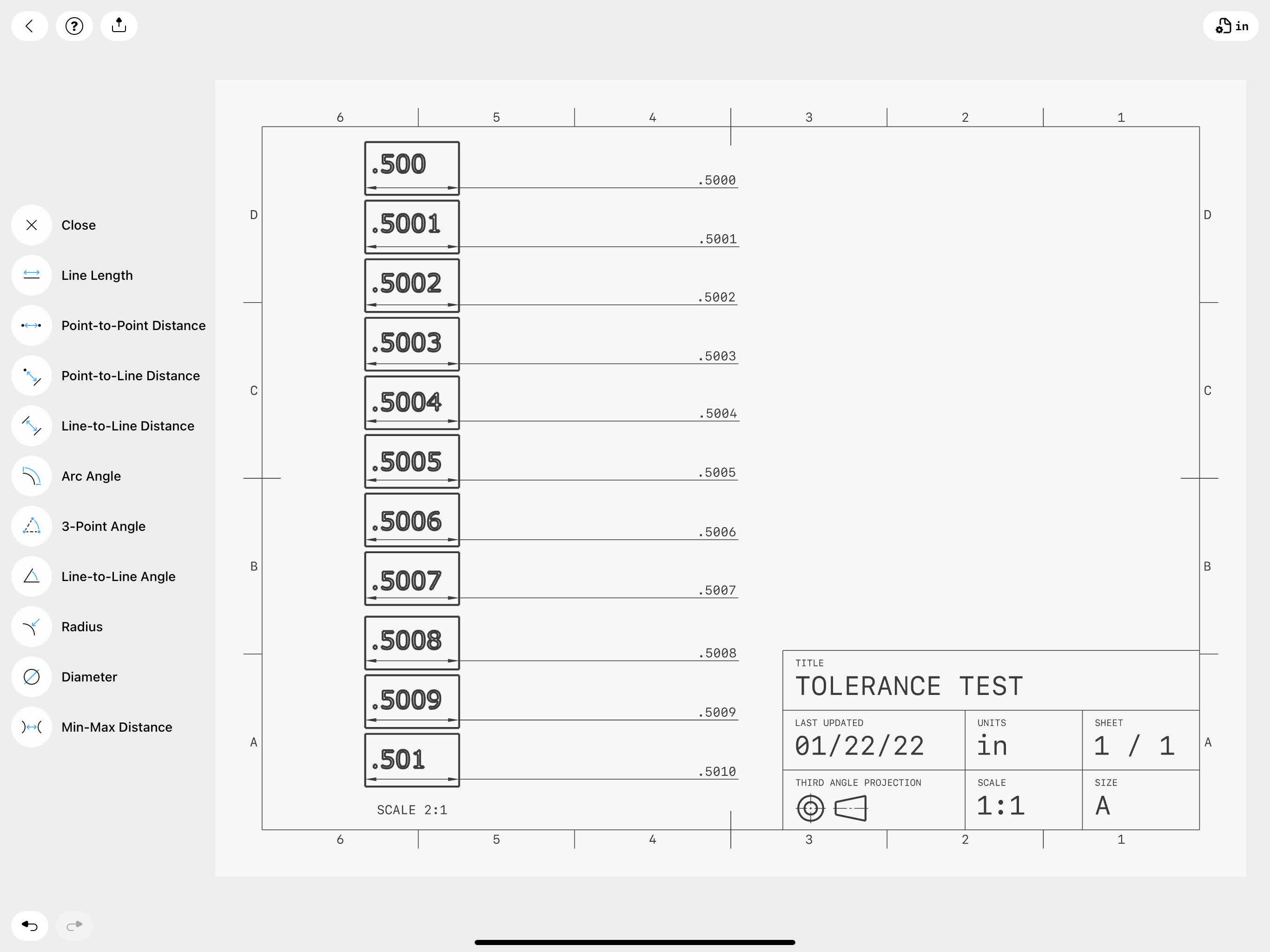
I made these “gauge blocks” with a marked dimension that corresponds to the dimension as input with the numerical keypad.
In the 2D drawing space, when the dimensional precision for the sheet is set to “.1234” the annotated dimensions are displayed correctly.
It’s the only place in Shapr that I know of that can display the .XXXX dimension.
I agree, if a dimension is entered as .XXXX” in the modeling space, it should display it in the modeling space/at the bottom of the screen, or at least be made an option.
I’ll admit, I haven’t used .XXXX dimensions much in my Shapr models for this reason of not displaying them/rounding until it’s annotated in 2D drawings, but I use the text notes in the 2D module to call out fits on a nominal size. Not optimal but it’s worked so far. Having tolerances will be even better.
Thank you for that great test and description, this is exactly what I was referring to in my original post. Like you, I have avoided inputting the fourth digit in my models. When I first noticed the display only reading .XXX after inputting.XXXX I had decided that Shapr would be merely a 3D sketching tool vs a 3D modeling tool. Then the other day I was making a 2D drawing of a model I wanted to machine and I noticed the option to display dimensions as .XXXX which led me to make this post. Your experiment has made clear that Shapr is capable of retaining dimensions as inputted, if only displayed in the 2D drawing. If I can keep all of my measurements in the actual model, it would save the step of making a hand drawn sketch with exact dimensions and then modeling off of the sketch. With the idea of adding text annotations I should be able to model my parts to accurate dimensions.
This is the number one feature that I would love to see in future iterations of Shapr, the ability to display exact dimensions to at least .XXXX”