Yes, I made this in Shapr3D and used the visualisation feature.
I had planned to upload a video of my workflow but I can rarely reduce the file size below the maximum 10MB
The thread was relatively straight forward to produce.
(@McD suggested importing a thread from McMaster-Carr but I’m not familiar with them. But, I’m curious now and will certainly take look)
However, I can’t see why one can’t revolve a simple profile to create the male then subtract to create the female.
(and before anyone jumps all over me… of course you will need to allow for clearance)
This can be done by creating the male thread slightly oversize the subtracting it from the female half and then re-make the male thread at the correct size and add to the male half.
You’ll need to create clearance at the root of the thread too.
(either in the od of the male or the id of the female)
I don’t have a 3D printer so can’t give advice on tolerances but I’m sure a little trial and error will get you on the right path.
(in my example I’ve allowed 0.1mm tolerance)
First I created the cylinder and shelled to create the desired wall thickness.
I then offset…
…and stepped down to accommodate the threads and cap wall depth.
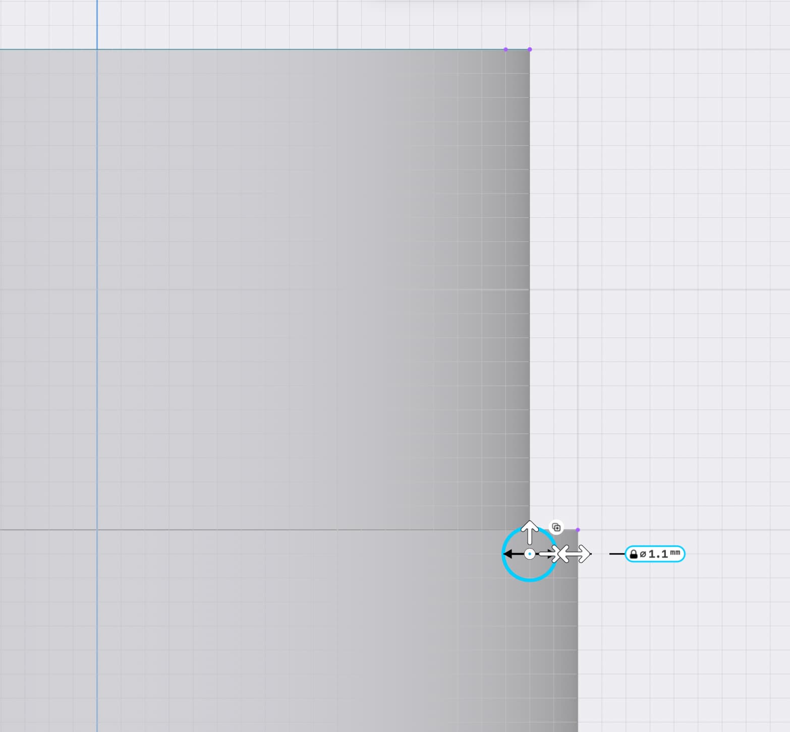
Created thread profile 1mm + 0.1mm = 1.1mm
I made sure to start below the surface.
Revolve desired number of turns.
I made sure to finish above the top face.
Split body to make thread start flush with top face.
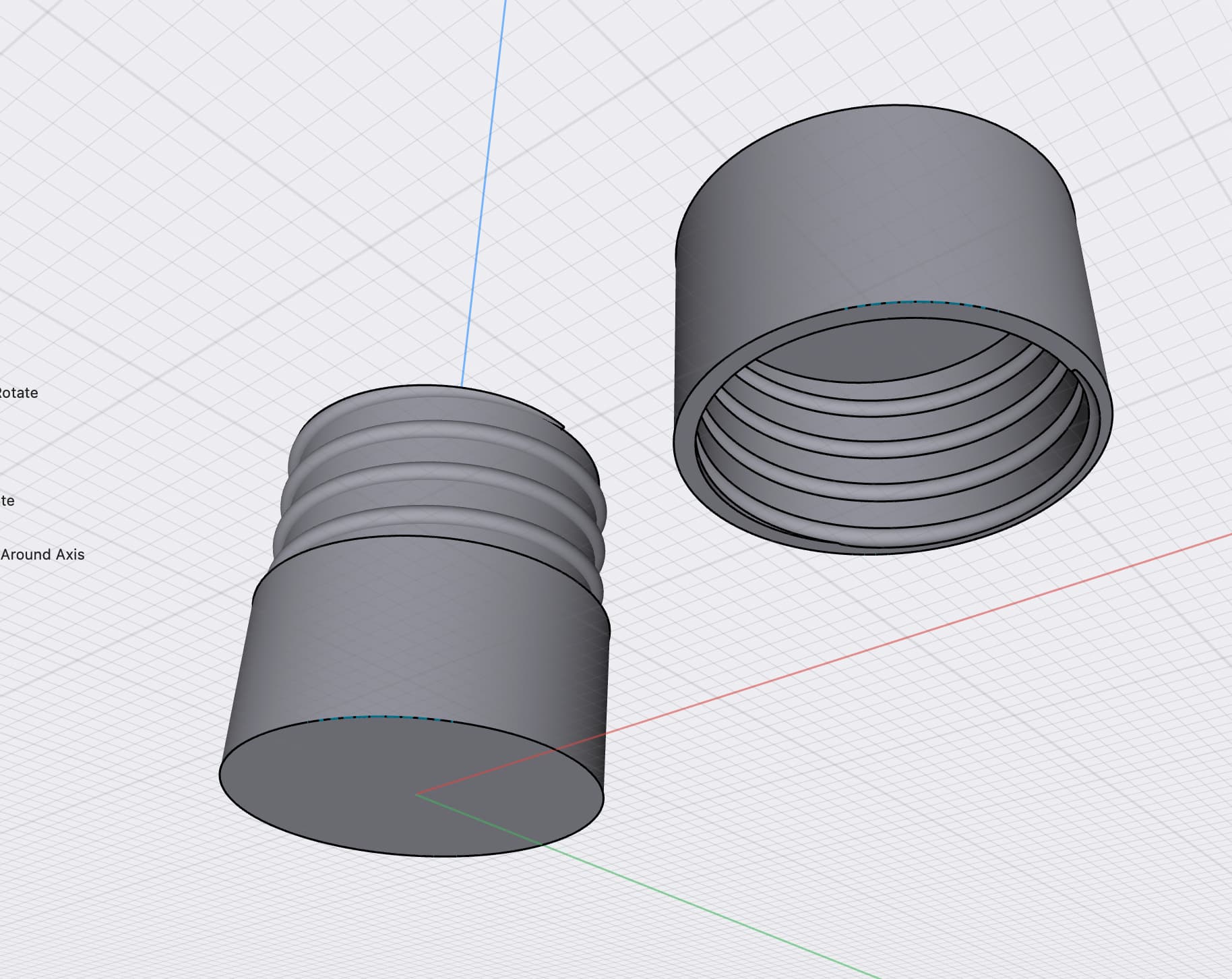
Created the lid.
Shelled to create the desired wall thickness to match the cylinder.
Positioned over main cylinder.
Subtract the oversized thread from lid.
Used offset to reduce the thread by 0.1mm to achieve a 1mm thread
Et Voila!
As usual, there are many other ways to achieve the same result and with a bit of trial and error, practice and patience you will find a solution that will fit your particular workflow/preference.