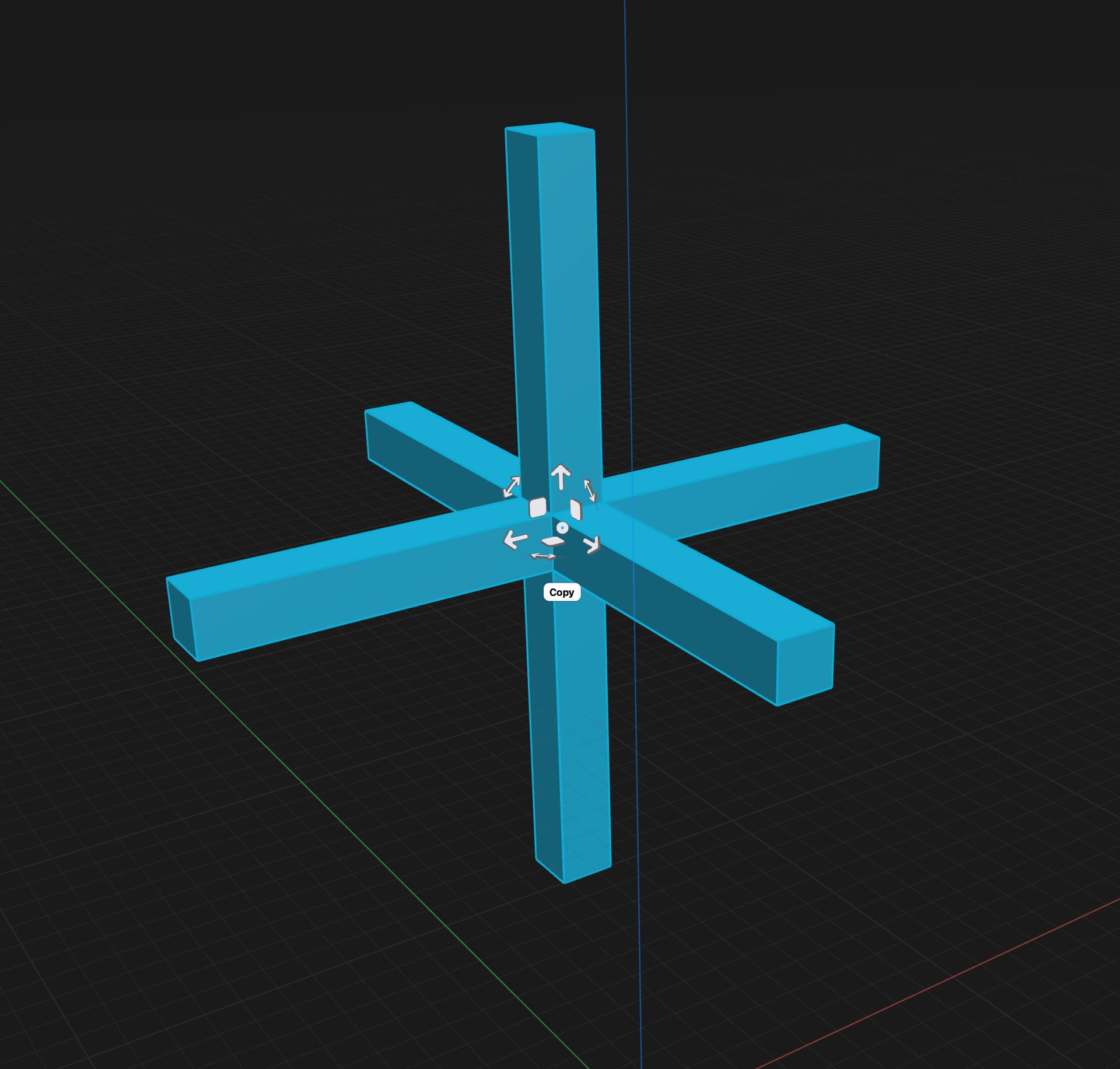
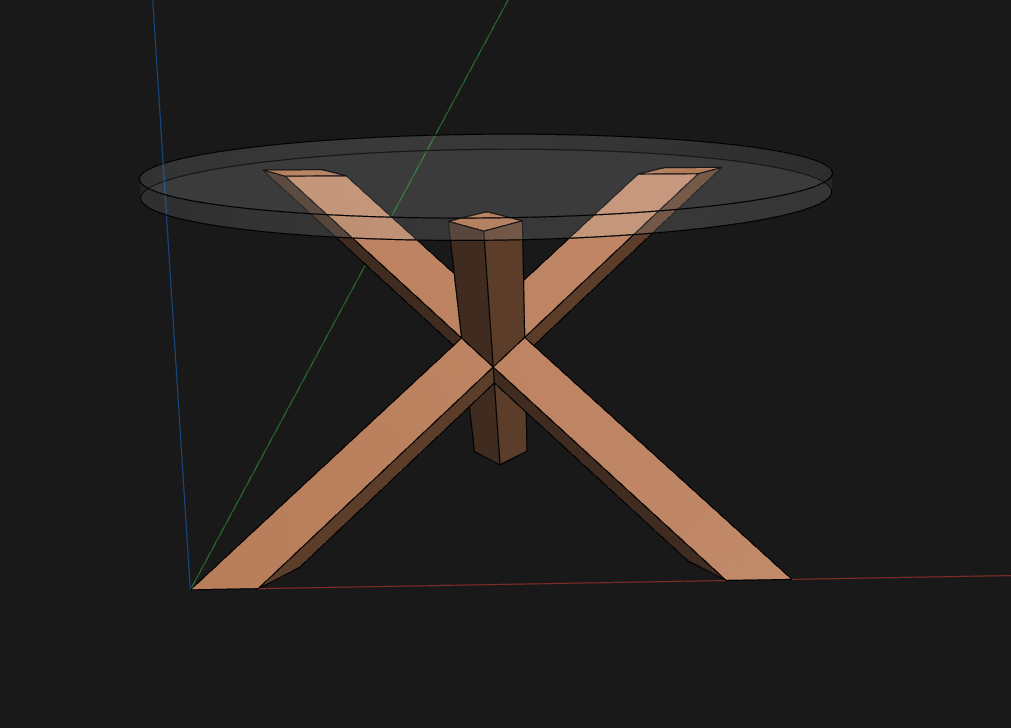
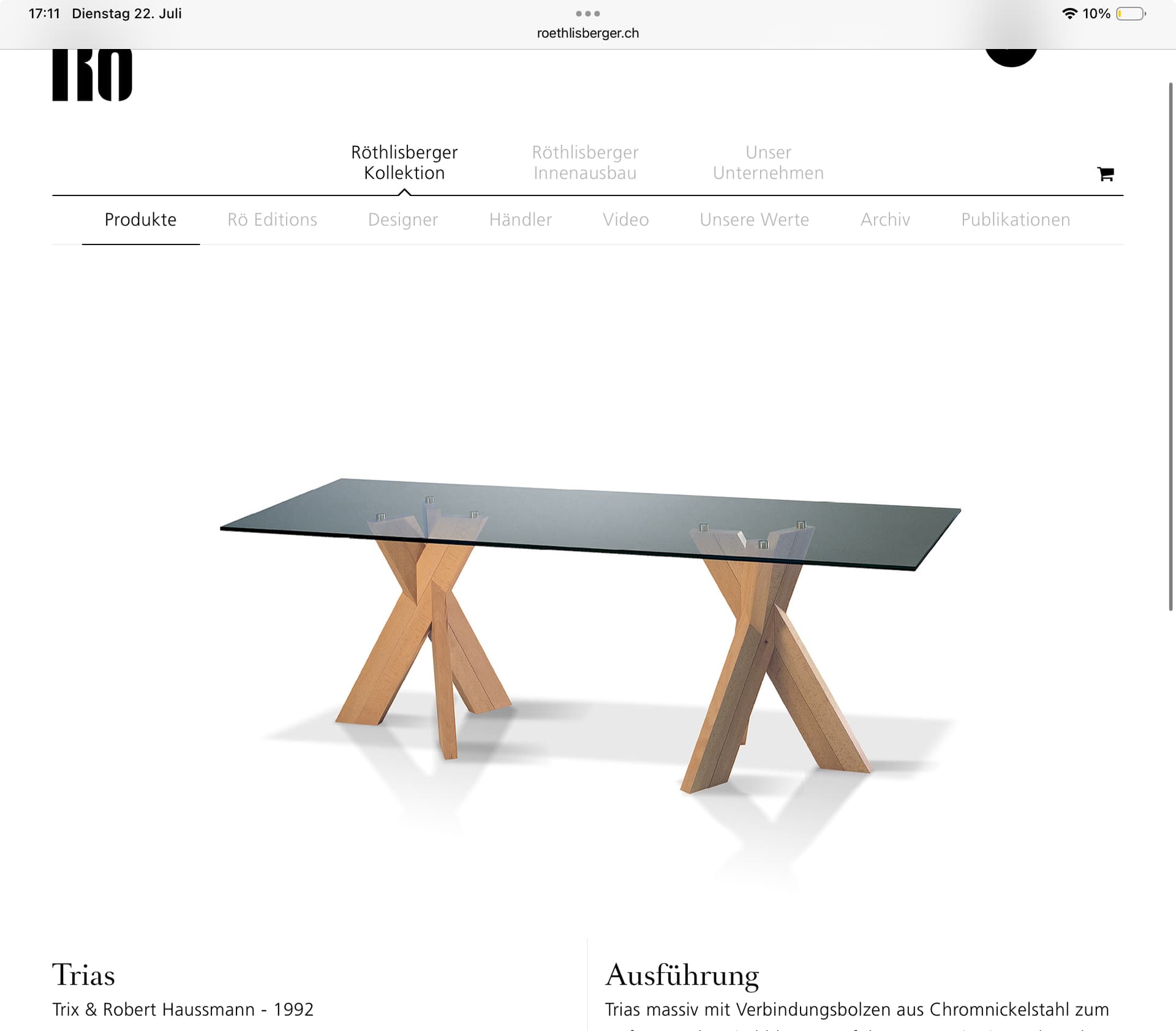
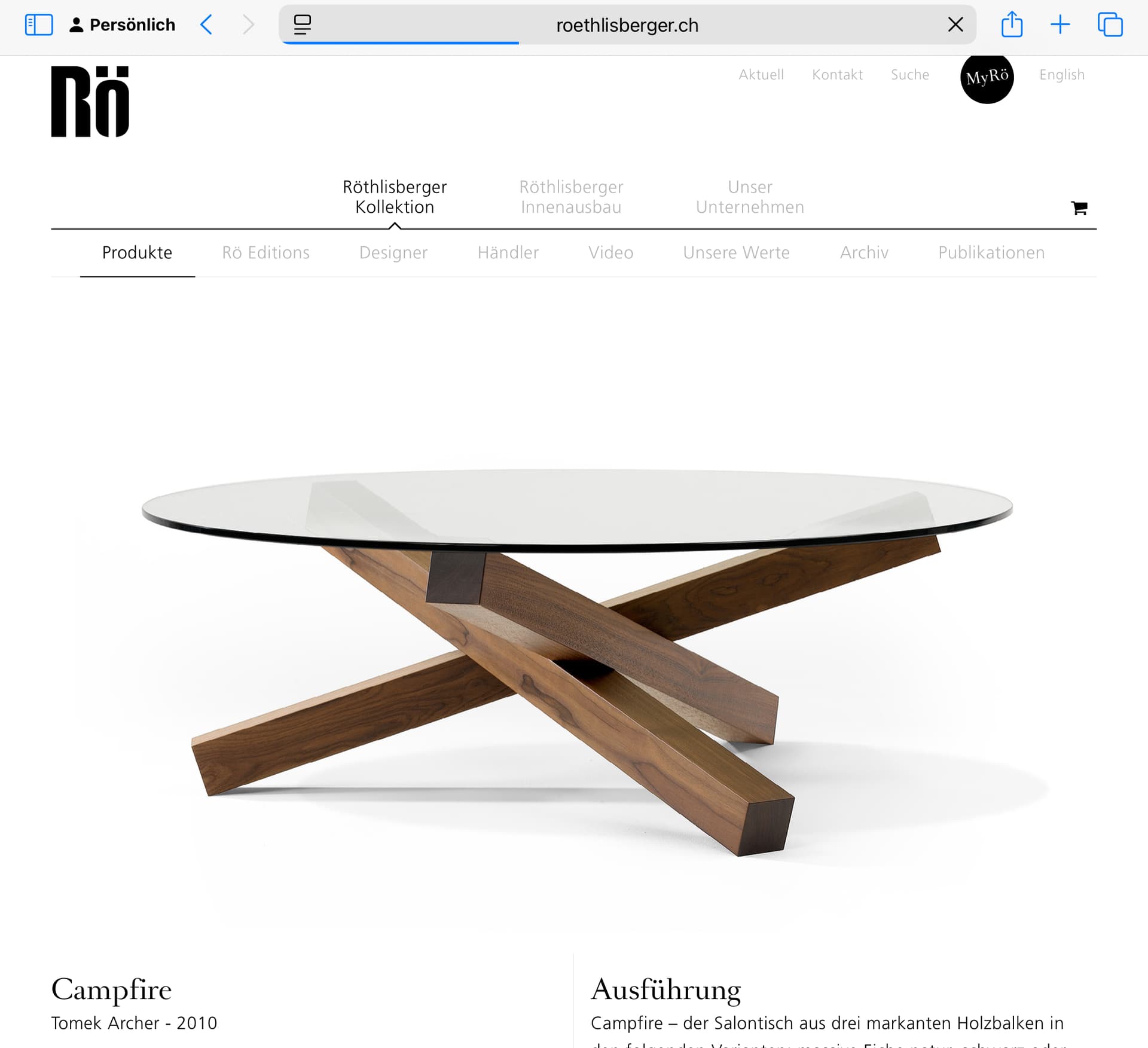
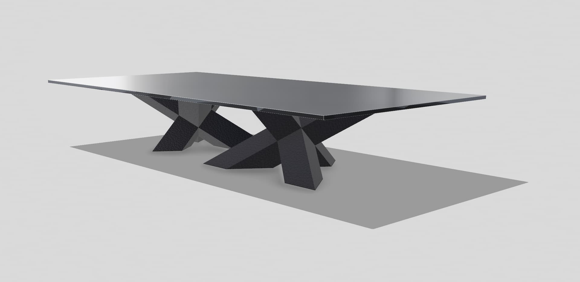
I am trying to draw this table base in shaper and having some issues. Cant quite figure out how to make it. I thought at first I could make a 3 way cross and then rotate it 45 degrees twice to achieve the shape, but it doesnt line up properly and leaves one leg longer than the other. Im pretty sure its just a matter of rotating it but Im not sure what angle or axis. Geometry is not my strength.

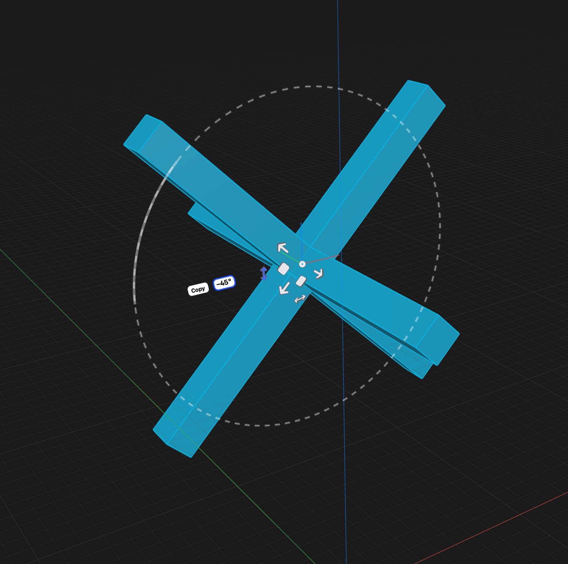
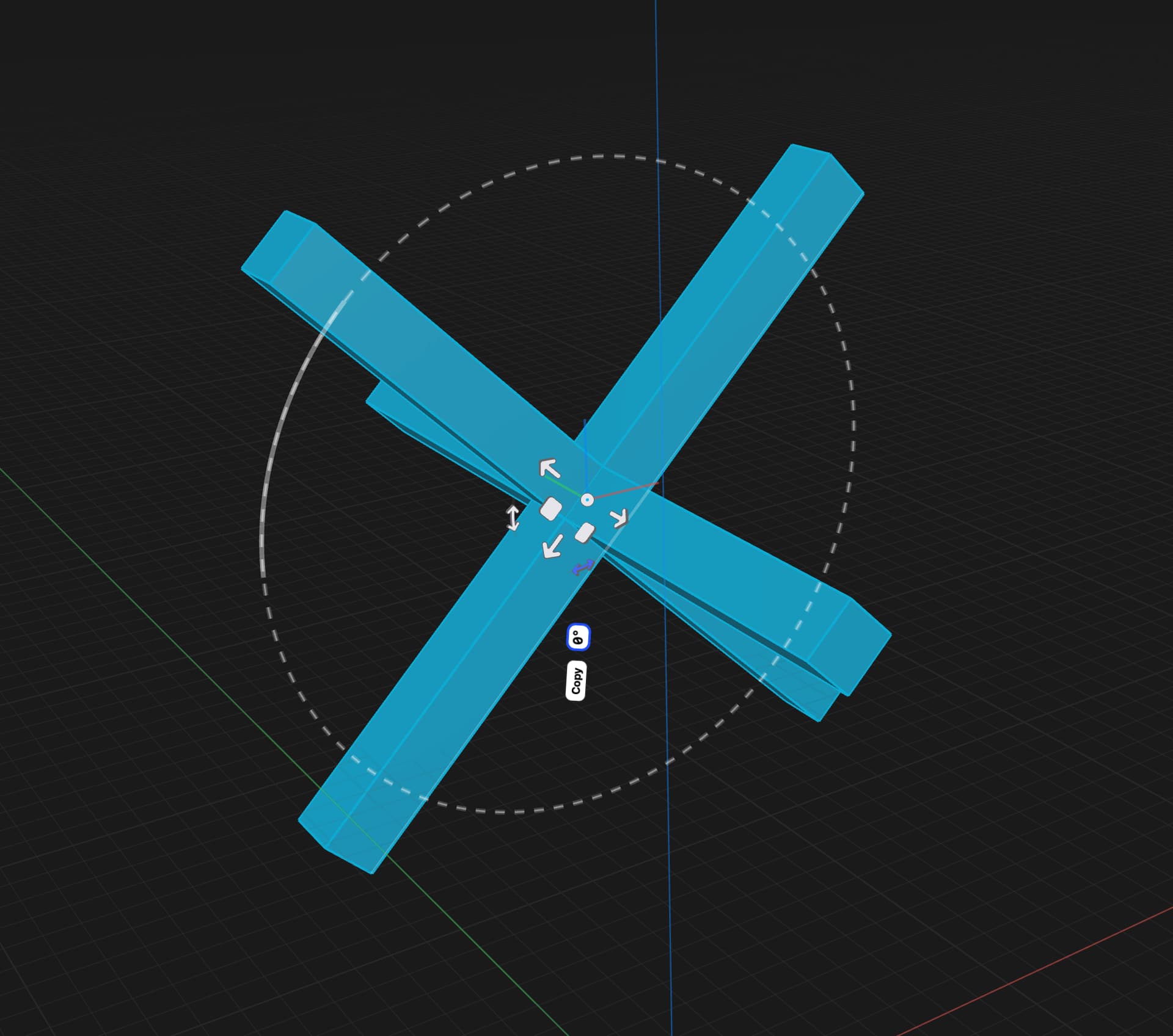
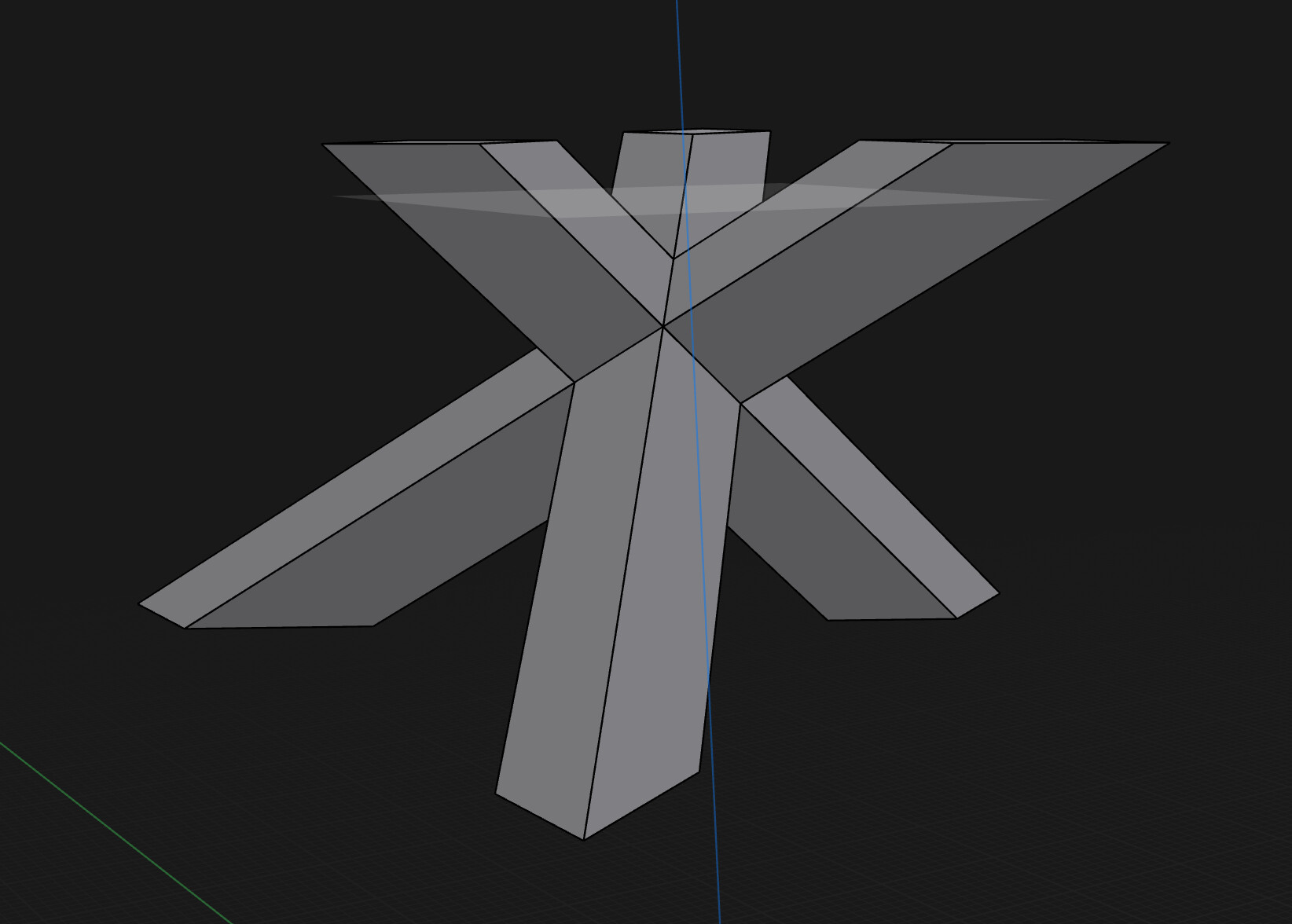
Two of the sides are longer than one of them when you do this. They should all meet the bottom at the same angle but they dont.
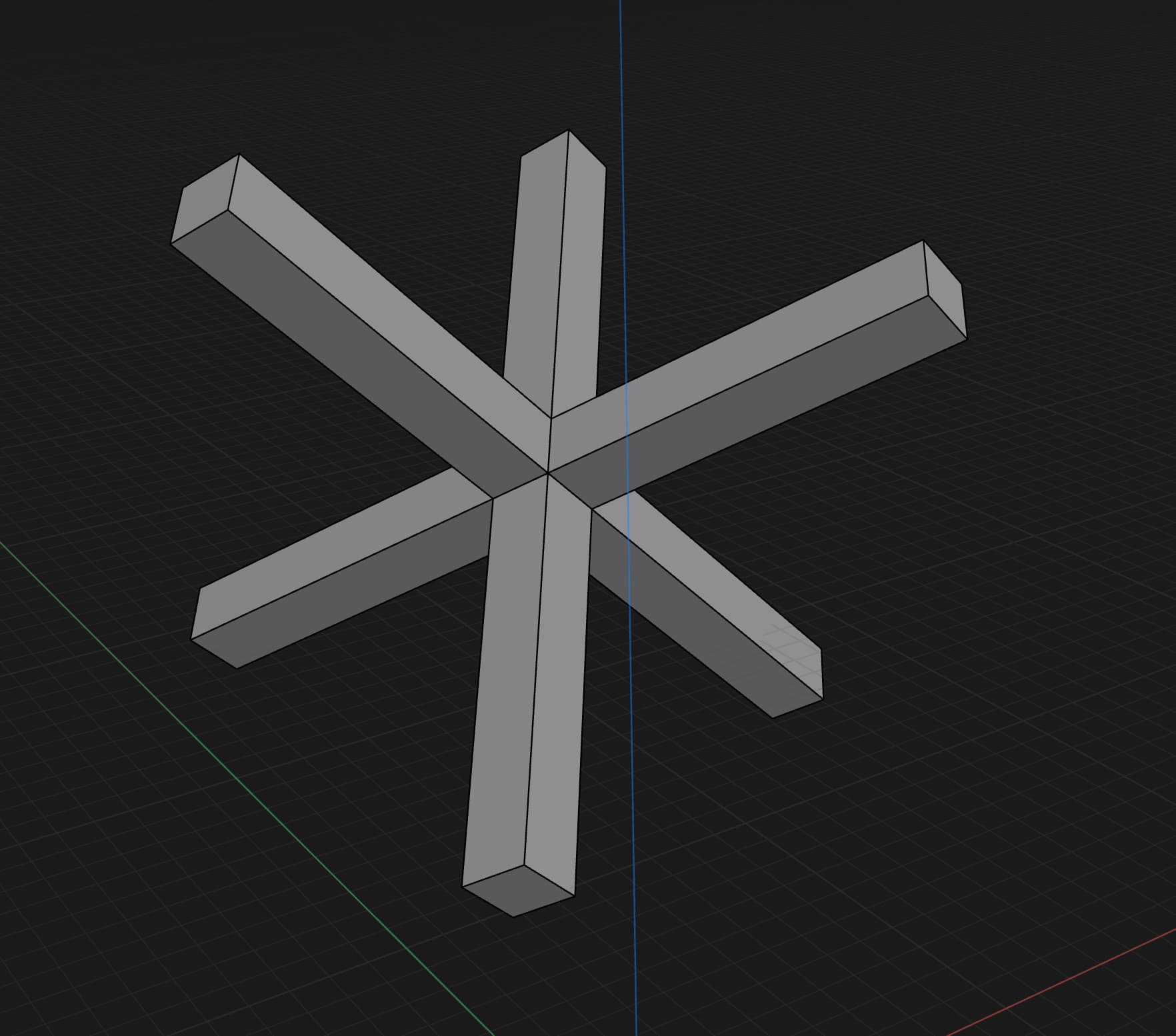
I see it, I think i know why.


That looks pretty close, how did you achieve that? Or can you share the model?
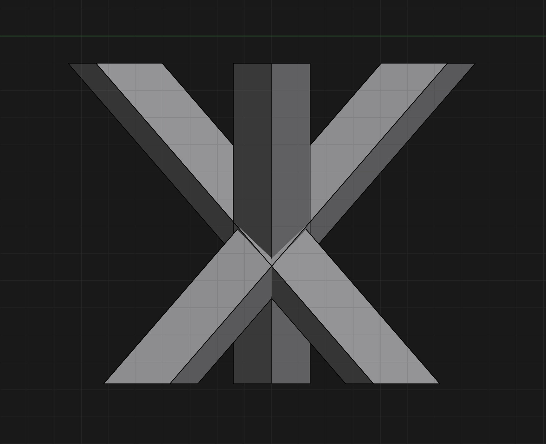
I see the legs at 90° to each other. I didn’t try to model it normal to the bottom plane. Instead I modeled it relative to the legs in place and did a final Align at the end.
Hey Tiger Mike, that worked perfectly! Question, how do you ensure the top/bottom is the same length when you move the plane up the 2nd time and the split body?
Probably the best way to make both ends the same length is to add a new plane to the opposite side and move it down the same distance as first plane was moved up.
If you need a further length adjustment after that, you can select all 3 upper and lower surfaces and extrude accordingly. Hope that helps.
I got it close enough. Now the tricky part is to determine what miter/bevel the saw should be set to so I can achieve that angle
Not sure if this helps. I added a plane to one end surface and selected the plane and one outer leg surface. The angle is shown at the bottom of the screen. Same for the other outer leg/plane angle. (Not sure if the measurement tool could work.)
Silly me…adding the plane not necessary. Just measure the cut end against the leg surfaces.
Gettin’ late here. ![]()

Interesting task. Thanks. ![]()
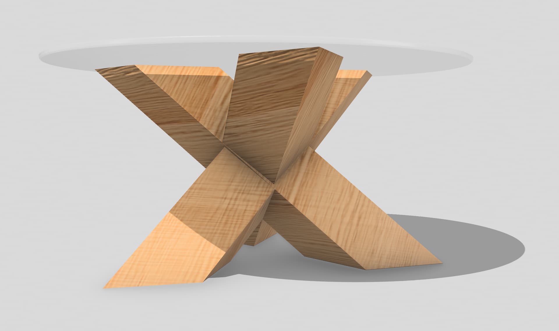
Here is my way of doing it.
-
First of all - sketch:
This is left lower piece mirrored to the right and then result mirrored to the top.
Thickens and height via variables. -
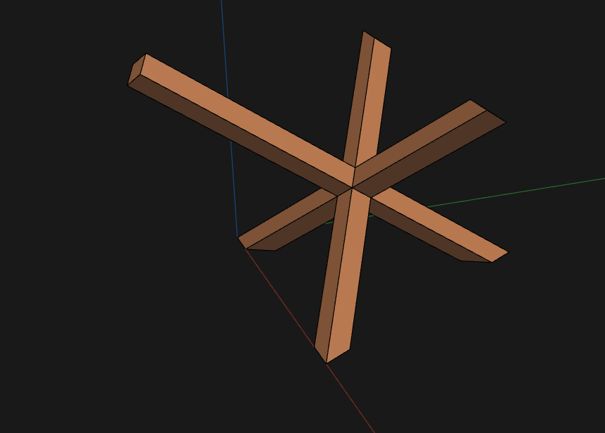
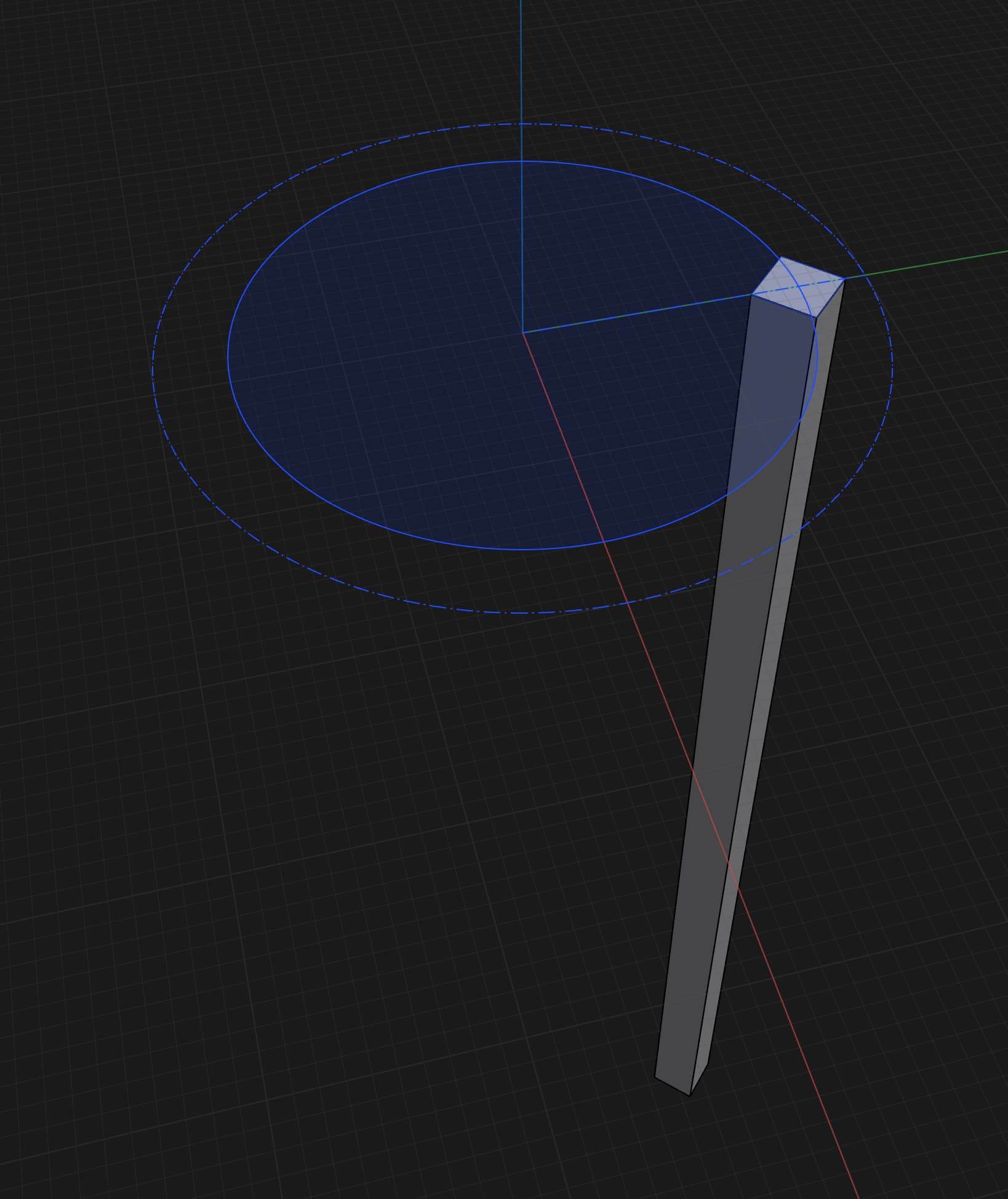
Extrude and rotate around axis on 35 degree
Thickness from variable -
Another sketch snapped to the previous geometry
-
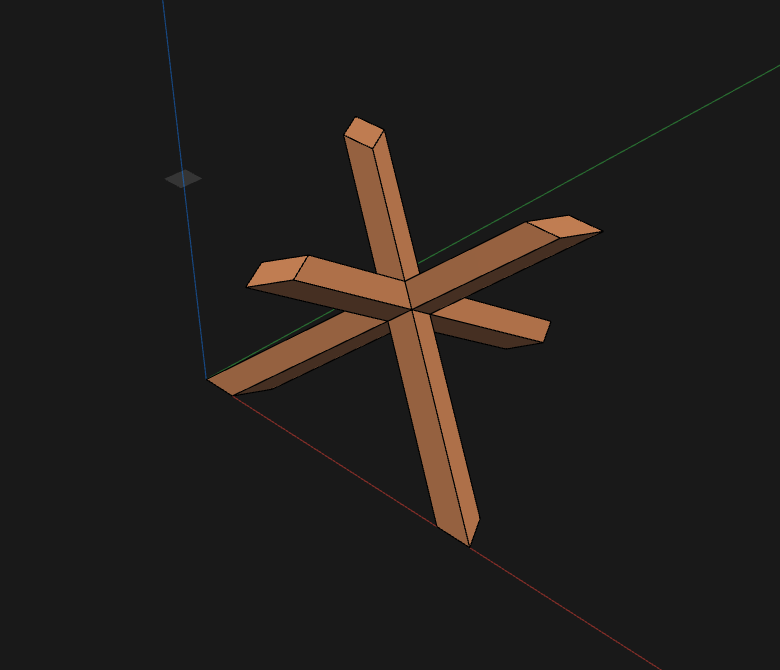
Symmetrical extrude, length from variable + 100mm just in case

-
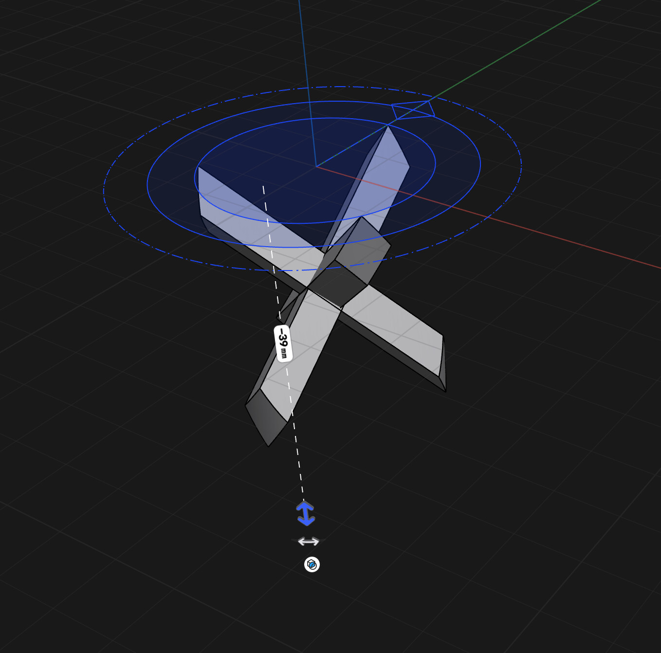
Cut the bottom using XY plane
-
Cut the top using offset plane with distance from height variable
-
Sketch the table and extrude it


To make bottom and top part of the legs equal length distance of top cutting plane need to be adjusted. Perhaps it can be calculated but I don’t want to dig deeper ![]()


Eine andere Idee.
Schreinerknoten / Carpenter’s knots
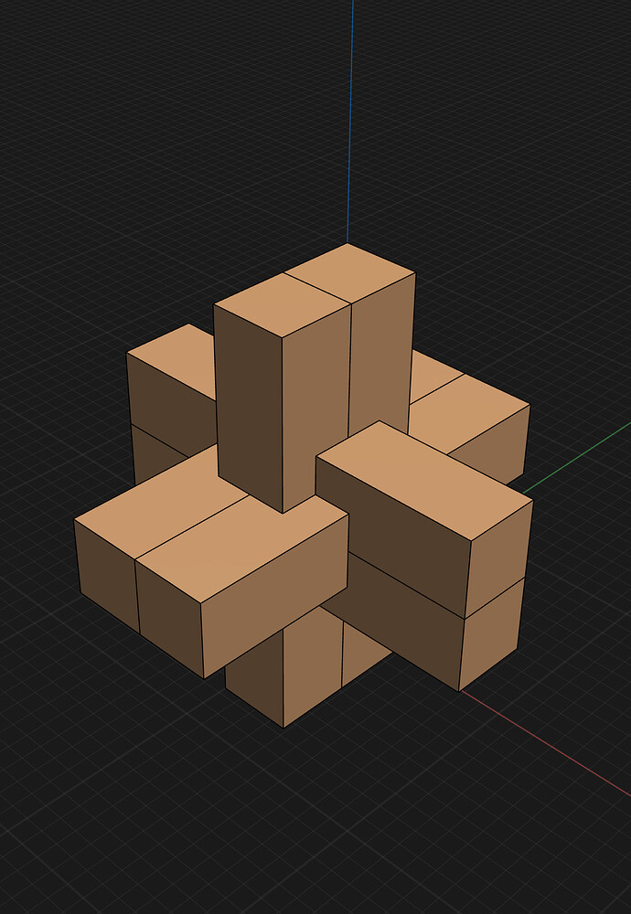
#Schreiner #Woodworker #Wood #Holz
Mit freundlichen Grüssen
Andreas Desiderius Haudenschild
So everyone pitched in, nice work BTW… except no one attempted the joinery needed to make this table “viable” for construction purposes. Joining 2 members, sure, easy. But the 3rd member?
@Oregonerd I can use dominos to attach the 3rd members, it should be fairly straightforward. What is more challenging is determining what the angle for the compound miter should be on the tops and bottoms. Simply checking the angle in Shapr3d doesnt work. I need to angle my saw blade and fence to achieve the correct angle.
I’m not a master, but I’ve been on the building side of things for 20 years… Looks cool but how you gonna do it? ![]()
I was the guy they gave the incongruous parts to and said “can you make this happen”. Uhh… Sure I guess.
Had to have a sense of humor…
Welded square tube sure. Joined wood, I’m sure someone could come up with something but will it hold up to the test of time.
And you the designer have a duty to come up with that method or you’re just a conceptualizer? ![]()