Solved - Aligning objects - Yet again!

Update from Shapr3d team:
We have just released the new 3d alignment tool feature with the 3.52 app version :partying_face:
This will allow you to simply tap on the body faces to get them snapped together.

Simply update the app and please share your feedback with us.
Here are more details about the feature:


Please. See attached screen shot.
Here we have highlighted in Red, a flat face, on a formed sheet Aluminium component (1.5mm thick). We also see a pneumatic cylinder, shown in its “retracted” state. I want to easily bring the cylinder perfectly perpendicular to the Red face of the component. Currently, I have had to draw a cube onto the end of the cylinder rod, translate a corner of the cube with cylinder onto the component face and then pivot the cube and cylinder in two directions until the cylinder “appears” perpendicular to the Red face! What a pain in the butt! And then I still don’t know if the fit up is accurate. Please show me how, without mentioning the phrase “It’s not Rocket Science”. This is a similar request to the guy trying to get his design parallel with the ground. Thankyou.

Tap with your Finger(s) on the Red Face, a Grid will appear, draw on this grid.

Or Add a Construction Plane to the Red Face > The Offset > set Offset to 0 [zero]

Sorry typo:

The Offset > should have been > Type Offset >

The Cylinder is imported. I did not draw it.

Not sure if this will work but it will only cost time:

Duplicate the File with the Added Construction Pane Offset from the Red Face.

Delete everything except the Added Construction Plane, Select the ACP then Import the Cylinder.
Hopefully the Cylinder will align or be align-able with the ACP.

Import the resulting File to your Original File.

Having tried the suggestion it proved to be a flop, sorry about that.

Given the features available in Shapr3D it is quick and easy to create Objects if you have sufficient detail or can obtain it from the Imported Cylinder it is worth assessing the possibilities of recreating it on the Plane where it is required.
The outer Casing of the Cylinder looks like a complex Extrusion, relatively easy to replicate if the end result is more about Form than Function. If you want something that ‘looks’ right mated to the main Object at exactly the correct angle it could be the way to go.

Alternatively if you created the Object and Red Face Gasket can you determine or ‘reverse engineer’ the Angles involved, then apply your findings to the Cylinder?

I admit it would nag me though until it could be fully resolved.
I am hoping for a resolution to satisfy both of us.

Other than that hopefully someone will chime in with a solution.

Yes, thanks for trying. I also tried it.

No. But thanks for trying.

It was anticipated that others would have offered alternatives or assistance by now. Hoping you have resolved the problem, I am still thinking about it. Even if you have completed your project please read on.

If you have found a solution that is absolutely great, it would be really useful if you would share it here.

Otherwise, do you have any information regarding the Sketch of the ‘formed sheet Aluminium component’?
During creation a Sketch has to be made on one of the three standard Panes:
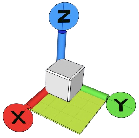
XY%20Orientation

XY; YZ; ZX:
or perhaps a Construction Plane(s) [CP or CPs]?

Do you have any information about the ‘Red Face’ lane regarding the set up of angles in relationship to any of the three standard Planes?
Such information may be useful to temporarily return the Red Face Plane to align with the Plane used to create the Imported Third party Pneumatic Cylinder? Importing the Cylinder and Snapping the two Items together should be straight forward. Except if it has been created an a skewed CP.

Alternatively, as previously suggested, double tap your Finger on the Red Face to provide a Plane on which to Sketch. Input your Component details or replicate the essential Lines in Sketches within the file below and then extrude appropriately.

This version of the Cylinder appears to be somewhat like the component you are using:


The details of this were taken from the internet providing dimensions to 0.01mm.
Educated guesses have been made regarding the Internal Details, Shaft Coupling, Piston and Cylinder Diameters. The information shows the ‘Shaft/Piston/Cylinder’ Assembly as being 1mm higher than the centre line of the Body, I have placed it dead centre. The Rear End has not been properly completed, my guess is that the Cylinder has a ‘closed-blank’ end?
The rear view showing the the Cylinder is the same as the front [Cylinder portion] with just a ‘filler’ piece added.
The basic Body dimensions are 130.65 high x 121.85 wide x 171mm long, with Fixing Centres 94 x 94mm.
It remains a ‘work in progress’ subject to any ‘adjustments’ being needed.

If you can provide the dimensions, interested only in finding a resolution, I will be happy to produce a Cylinder to the exact dimensions, of your Component. If you do not NEED to do this I would still welcome the opportunity to complete this project as it will be at least one more method tried and either accepted or rejected.
You would also need to supply an Uploaded Copy of your Design MINUS ALL detail, except a CP formed by placing it directly on the Red Face [i.e., Zero Offset]. However some means of accurately positioning the Cylinder on that CP would be required, e.g., Mounting Hole Locations.
Either Cylinder, i.e., yours or the one on this page mounted on the virtually empty new CP Design would be completed and Uploaded, by me, so that you could transfer it to your copy/duplicate copy of your full Design.
Excluding the Location Point(s) the only aspects that will be visible publicly are the CP and the details of the Pneumatic Cylinder, the latter probably being commercially available anyway.

I have other commitments for the next two days but hopefully an outcome would become available during the weekend.

Here is the File:

Pneumatic Cylinder.shapr (496 KB)

Thank you for replying. Disappointed, with the inability to complete what I am told is a simple operation in other Cad Systems.

In my job, I design and build Fixtures to hold components allowing other components to be assembled to them. In this case, I receive the “Pressed” Aluminium component from the pressing process. I then locate the component accurately in a fixture and the add threaded inserts, creating an “Assembly” that then is fitted into a car.

So I download the customer drawing of the component in Iges format and design my fixture around it, pulling in cad models of “off the shelf” components from the respective manufacturers website, I do not waste time redrawing peripheral components who’s cad already exists. I obviously need to align all the parts, hence my problem!

I will try to somehow align the face in line with the cad axis.

Regards Richard.

Thanks for your reply, best wishes for a successful accurate end result.

Thank you. My apologies if my reply sounds terse. I’ve been getting on really well learning Shape, it’s cost me £1250 to set up and so I am keen to master it. I can live without the ability to produce 2D dimensions required to manufacture, but any additional restrictions take away from it’s flexibility.

Your reply is in great depth and a little complex for me but I do appreciate your help.

Thank you, regards Richard.

I think I have a solution. It is a work around, perhaps a bit tedious, but it does work. I spaced 2 objects apart at a compound angle and with a slight twist to the one I want to align.
The steps are-
Translate the tip of the object to the desired surface.
Create a construction plane at the surface of one of the angled surfaces (0.0 offset)
Hide the destination block and sketch an arbitrary rectangle and create a body
Remove that body from the destination block.
This gives you the exact angle of the source object to the dest object (highlighted in blue)
Use that angle to rotate the object so that one edge aligns with the dest surface.
Repeat the steps above for the other angled surface.

I hope this is clear enough for you. Here’s a link to a video I uploaded to YouTube as the file is too large to post here. The video simply steps thru the process (all redos).

I hope this helps. Let me know if any questions.

Regards, Mike

Hi Mike

Sounds good. I will try later this evening. Thank you, regards Richard

Hi Richard,

A couple of comments. At the end of the video I purposely embedded the source object into the destination surface and subtracted the difference. This confirms that each of the vertical corners of the recess are identical.

For your situation, you might want to create construction plane above and parallel to your destination surface. Use the plane to create a dummy body for the purpose of doing what I did to align the source object relative to it. Then remove the plane and temp body and locate your source object to the desired location on your destination body.

Regards, Mike

Sorry, one more thing to mention. After you get the exact angle for rotation, you need to place the pivot point for rotating the source object at the 3 edged corner that you initially translated (the corner that is touching the destination surface).

-Mike

Brilliant Mike thanks. It’s do-able and accurate and that’s the main thing. Hopefully this can be condensed to one swift operation in time.

Regards Richard.

Really pleased to see you got the result you needed Richard.

Sincere thanks for your invaluable input Mike.

You are most welcome (Richard too). Glad to help.

Regards, Mike