I really appreciate your help. Let’s say it this way: if a end mill (in this particular case diameter 2 mm) cuts a cam or curve into a tubular solid body, the cam or curve will not have more than 2 mm width. Let’s assume your yellow brown cylindrical body is the end mill of my machine, you see the curve must be much wider to make it possible to move the yellow body or bolt.
This is not the case if you make this part on the milling machine. 2mm end mill = max 2 mm curve width.
I started with prototyping prior to shapr3d and now i need a proper 3d model for serial production on xometry.
PS: This is the solid part how it has been manufactured. Well there is a thread on the outside of the bolt but this doesn’t have any impact on the curve . The curve has a with of 2 mm, +0.1 mm. the pin has diameter 2mm. but if i create the model on shapr3d the curve needs a with of minimum 2,5 mm to make it possible to move
Sorry that I don’t quite follow. Given your example, in order to fit a 2mm ball, you’ll need a 2.5mm end mill to create? (This is more or less my understanding.) You can alway widen the slot- either initially or afterwards like below. Anyway, good luck.
Chris, I think @TigerMike gave a great answer of how-to.
If you revolve a rectangle with edge of A, and give it some height, get the shape you are after. If you have an angle (relative to the end of the cylinder) the size of the rectangle is not going to be the size of the bolt, you’ll need to calculate that.
cosθ = B/A
A cosθ = B = 2
A = 2 / cosθ
So if you have a 30° pitch, you’ll need to use a rectangle in Shapr3D ~2.3 tall to cut out your slot of 2mm.
My trig is a little rusty. If I missed something, somebody, please correct!
I tried revolving a rectangle that I rotated slightly by guessing an angle on a 180 rotation and some arbitrary rise. The slot is nicely perpendicular to the tube along the path. Where it goes wrong in at either end of the cut. Revolving around an axis does not account for the tool width?
Yep, this is what I was trying to get at with my explanation haha. The limits within the system. Mike got close, but even then if you pause on the section views you can see the “cut” comes inwards to a taper slightly. What Chris needs is a perfectly square cut. Every variation I tried the end could never have the filets meet evenly.
Thanks Bob, this was my first attempt. I did the math and I used the revolve tool. My calculation shows distance A = 2,33 mm but It still doesn’t look like made on a mill. The picture proofes what I mentioned above, the pin has OD 2 mm and the Distance A on the solid part has 2.08 mm and this is enough to move the 2 mm pin inside the slot, ways below the calculated 2.33 mm.
The measurement points are located on the longitudinal axis, regardless if i did the measurment at the end or in the middle of the slot, they are pretty much the same:
Hey, thanks for your input. unfortunately this wouldn’t solve my problem. I used revolve tool, sweep tool with the same effect. I need a body in shape of a end mill which I can sweep through the cylinder, a face revolved or swept through the cylinder does not bring the right results.
Yes, the software is limited, i need a body in shape of the milling tool (cylindrical) and this must be swept through the cylindrical workpiece. I dunno if this is possible with shapr3d
OK. I was visualizing rotating the part when you cut it. Here is a try of keeping it clamped down and running the mill thorough it. Does this look any better?
It’s not perfect, but it’s a combo of what’s been proposed here with an extra few steps to get the ends square cut like you’re after. Links below to the Shapr file so you can download and check it out for yourself and modify as needed.
Almost there… I did a rough estimate, playing around.
Two interesting problems; the ‘slot’ and ‘end caps’.
The ‘slot’ seems to be (aprox) formed by an ellipse. I estimated (only) this in another system to import for sanity. I looked to see if there is a simple perfect way to do it geometrically, but I cold not see it. To find the precise form of the slot I would have to fall back to a quite complex algoritm.
The 'end caps, is really complex to get perfect, I simply used a slightly oversized ‘pin’ as a guide to subtract.
Hey Thank you very much for your ideas and input. The solution provided by you looks pretty good. The problem is, I need this 3D model to get a quote by a online manufacturer plattform, they need a 3D model to make a proper programming for the CNC machining. Long story short. The slot , made with a mill ( OD 2 mm end mill) would not have a trapez shaped slot in a section view, so this would be confusing. The only way to make it like made on a mill. A cylindrical shaped body must be swept throug the larger cylinder in order to “cut” out to the section. But I think it is not posible to sweep a body with shapr3d
I need to compute the helix angle at the base of the milling tool, based on the revolve’s angle and elevation.
In my exemple, the revolve angle A is 120° for an elevation E of 10mm and the milling tool length L is 5mm.
So the angle to compute is ATAN(2*xPI/360xAxL/E) = ATAN(2x3.14/360x120x5/10) = ATAN(1,0466) = 46.3°.
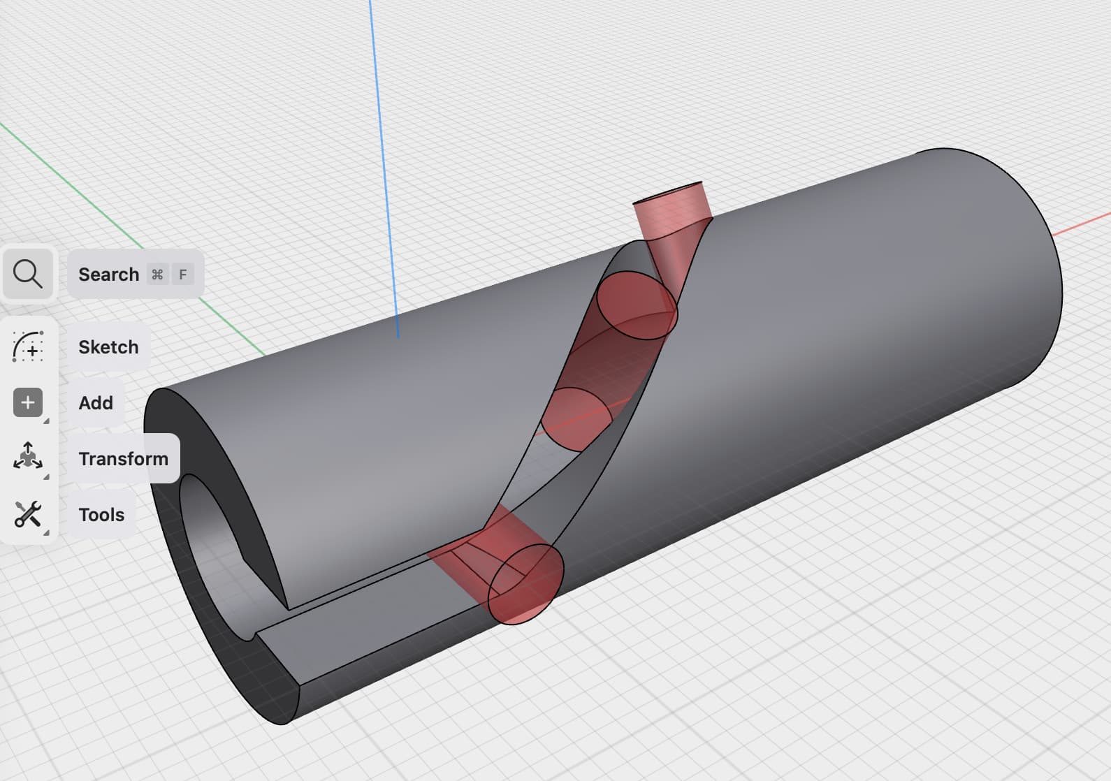
I then use half of the cross section of the milling and revolve it along the Y axis with an elevation of 5mm and an angle of of 46.3°, so it creates the shape from which the helix part of the tool’s path is created.
Then I revolve the convex surface created along the X axis with the 10mm elevation and the 120° angle.
(You can revolve not only planar face but also complex surface).
The video shows it all.
I include the .shapr file (thanks to history, all the steps are recorded and can be replayed by moving the breakpoint). Slot milling.shapr (122.7 KB)
Hey, awesome work!! in your model the 2 mm pin is able to slide, i made the same calcs but with A= 160 degree, E = 4,5 mm and with the same milling tool lengst 5 mm ATAN(2x3.14/360x160x5/4,5) = ATAN(3,102) = 72,136°.
But the the part i revolved showes stranges edges ( Slot milling 1)
and the end of the slot has also a wrong ending ( Slot milling 2)
I attached the shapr file and a pdf hoe the slot should look like. I will pm you maybe i have a job for you:-)
Again thank you for your input, i think it is defenitely the right direction.