I saw your PM and gave a try this morning, but I’m afraid we are reaching the limit of Shapr’s capabilities (or mine’s ).
Your angle is much bigger than the one I used, so the curvature is also much bigger, and the program struggle to do it right.
I tried to revolve the concave surface instead of the convex (it is easier to compute the revolve I think) and it gives you a better shape, but it does not solve the wrong ending of the slot (you must complete the ending by move 4.5mm + rotate 160° the milling tool but it does not perform better).
I tried also to do several loft, with multiple 3D guides, but didn’t succeed to get the loft working, for the same reason of high curvature I guess.
So at present, I have no idea how to do it better. I will keep thinking about it in background, and will PM you if I find a better solution.
Sorry if this is OT, but I find it interesting to play around with…
The slot , made with a mill ( OD 2 mm end mill) would not have a trapez shaped slot in a section view, so this would be confusing. The only way to make it like made on a mill. A cylindrical shaped body must be swept throug the larger cylinder in order to “cut” out to the section.
But if you sweep a cylindrical pin you do get a trapezoid shape:
I simulated the mill (cylindrical shaped body) 16,8mm traveling 90° in a slope of 51° with a cylinder diam 100/50 and the resulting slot (radial) becomes a trapezoid 20,7x29,7 with slightly curved symetrical sides resembling something between a (half) ellipse 12,7x0,8 and an a catenary/parabolic arch in an angle of 2x10,17°. 16mm pin inserted.
But when it comes to real manufacturing, and I made this part pretty often, there is no trapezoid form and a manufacturer will have problems to do the programming on the cnc mill or he will be confused. I appreciate your support, unfortunately the pin inside the slot must rest on a perpendicular wall of the slot and not on an edge, and a end mill like i used make no trapezoid slot.
I think @BKE is right and @Chris07 experience is not wrong : the shape is not a perfect rectangle, but with the parameters used by @Chris07 it is so close to a rectangle than the difference is probably not noticeable : about 0.05mm.
Here is an animation using @Chris07 parameters, with 5° steps from 70° to 90°, with the cutting plane set at 80°.
At 70°, the mill machines the bottom left corner, at 80° it machines the top left+right edges, and at 90° it machines the bottom right corner.
The superposition of all the cuts gives the final shape, which is not a perfect rectangle but very close to it at the intersection with the tube.
I did this animation trying to understand the wrong cut ending, and I think I found a way to correct it, even though I don’t understand why, which is not totally satisfying. I will post the solution soon.
PEC
Long story short, for some reason I don’t understand, when the angle of the helix is a large number, the start angle of the half mill tool that I first revolved is no longer vertical but must be rotated by an empirical value.
The yellow (1) is the one used in my previous post, the green (2) is the one that gives the correct result.
The end part of the mill is unchanged.
As the rotation angle is determined by trial (thanks to parametric version :)) in order to have just one angle to change in the step named “corrected angle”, I add a new revolve step using the end face of the previous body and revolve back with a new angle.
I also use the concave face to do the tool’spath and move the initial shape to the end to finish the tool’s path.
But this 3D is possible to create in Shapr3D. (Though exact mill of this is complex as the mills movement has to be combined with an axial movement, otherwise not creating the correct symmetrical sphere.)
Hi everyone. I’m also new here to this forum, though I’ve been using Shapr3D for a few years now. This is a fascinating problem being discussed here, and well beyond my capabilities to solve, or even follow the ideas being discussed here. But I now have the exact same issue; I must produce a viable 3D model for CNC machining, though I’ve produced various prototypes on a manual mill already. I’m only looking to revolve through 120 deg, to height of 2mm to accommodate a pin that’s 8mm. My question is; should I hire a professional CAD modeler to build this? Or should I have a conversation with the CNC shop about what my expectations are? Many thanks for any input, and apologies for not quite being able to follow the solutions offered.2025-02-09T23:00:00Z
If you want to cut a slot through the side wall of a tube, for operation of a captive pin. This is quite easy for anyone with a 4 axis CNC machine (XYZA).
Manually programming that operation is fairly straight forward for a skilled CNC operator. They will just need to know where you want the slot.
Reading again that thread, I realize that the “additional rotation of an empirical value” that I applied at one side of the mill is not empirical at all.
If the mill tool starts at 1mm and extends to 5mm from the rotation axis, then there are actually 2 angles to compute using the same formula as before:
the rotation angle of the end of the mill, as previously, using the 5mm distance
the rotation angle at the start of the mill, using the 1mm distance
I missed the second computation and intuitively replaced it by offsetting the mill side by 1mm. Doing that performs actually a linear interpolation of the rotation angle, valid only when the angle is not too large but the real computation involves arctangent of the angle, which is not a linear function.
So, doing the correct computation gives:
end angle rotation at 5mm from the axis = ATAN(2x3.14/360x160x5/4.5) = 72°
start angle rotation at 1mm from the axis = ATAN(2x3.14/360x160x1/4.5) = 32°
while the linear interpolation gives only 72°/5 = 14.4° instead of 32° and the “additional rotation of an empirical value” leaded to 42°, a bit overestimated vs the exact value of 32°.
Even with the correct start angle, the mill surface used for the second revolve is still an approximation because the revolve is creating the surface with a constant angle’s slope while theoretically the helix’s angle should also involve arctan.
So in order to minimize the error, it is better to compute the face rotation as close as possible to the surface of the tube to cut, in the current case at 2mm and 4mm instead of 1mm and 5mm as I did previously.
start angle at 2mm = ATAN(2x3.14/360x160x2/4.5) = 51,1°
end angle at 4mm = ATAN(2x3.14/360x160x4/4.5) = 68,0°
I enclose a corrected version of the .shapr file to reflect this better understanding. The slot’s error now is around 1.5µm instead of 11µm before, so good enough for almost any manufacturing process Slot milling V2.1.shapr (263.2 KB)
welcome to the forum.
I think this is what you need.
I arbitrary selected 5mm for inner tube radius and 8mm for outer radius, but you can edit the dimensions directly on the sketch (as well as the pin diameter to provide clearance for instance).
If you change the inner and outer radius, you will have to change 4 parameters in the history:
use your calc to compute atan( 6.28 / 360 x 120 x inner_radius / 2 ) and replace the 79° by the new angle (keep the negative sign)
replace 5mm by the new inner radius (keep the negative sign)
compute ( outer radius - inner radius ) and replace 3mm by the new difference (keep the negative sign)
use your calc to compute atan( 6.28 / 360 x 120 x outer_radius / 2 )
compute the différence between this angle and the first one calculated at step 1 and replace the -4° by this difference (keep the negative sign)
Wow…. Just wow. That is really quite a reply and solution you have given to me there.
Most of it still continues to go over my head, but you’ve presented it in such a way that I can still obtain an accurate result with my own values.
I’ve done lots of clever and innovative stuff in my career (I work practically, with my hands. The designing and manufacturing component is more of a recent adjunct to my real profession), but when I come onto forums such as this and see the contributions many of you make I am blown away by the enormity of the ideas and will to further enhance the collective intellect.
Thankyou.
Hi Kimchi
Here is my effort.
I have treated it a bit like doing the machining process.
So I create the tool to cut the slot, and put it at the start position.
Now split the tool in half at the angle perpendicular to the direction of travel (use a plane to do this).
In this case I want to rotate 12.566mm (12mm*PI/3) and rise 2mm, and using trigonometry I get 9.0433 degrees.(Shapr3d needs a flat face to revolve)
Rotate the leading tool half 120 degrees, then move it up by 2mm, to be at final location.
Now Revolve the square face of the lower tool half 120 degrees and raise it 2mm. This will now meet the other tool half.
Union all three pieces together to make one body.
Finally extrude the tube body, and use boolean functions to minus the tool slot from the tube body.
A Scan of the calculations for getting the split angle right.
I used a tube with an ID: 8mm, and OD:16mm
I do the calculations using the centre radius of the wall, hence r=6mm or D=12mm.
I made the cutting body (tool) 4mm Diameter and 6mm length and positioned it to cut the tube wall with 1mm protruding internally and externally.
I also used the 120 degree rotation, hence 360/120 = 3 in the calcs.
The process is fairly easy, but you must follow your calculations, and the angle of the tool split is important. As Shapr seems to work to 4 decimal places I suggest you use 4 decimal places when calculating, to minimize geometry issues.
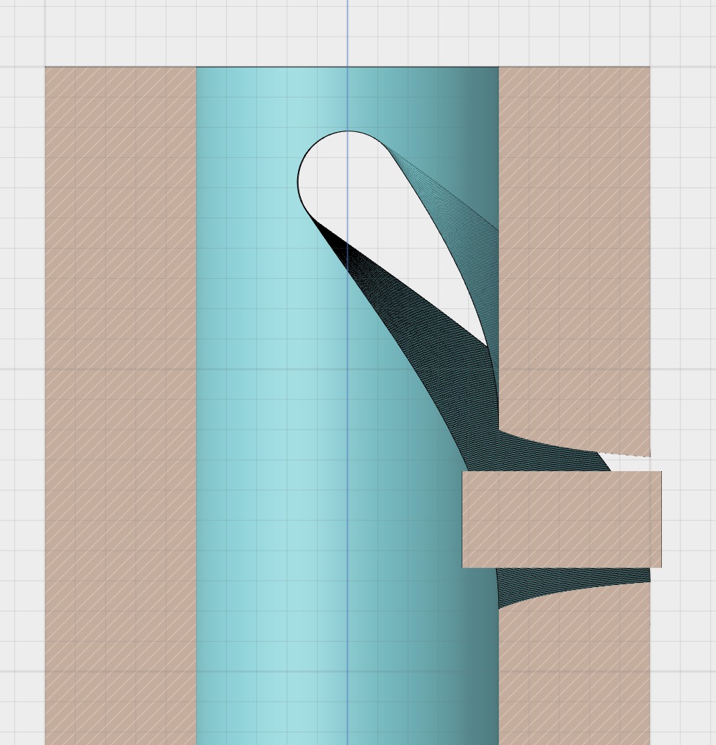
I use a twisted plane which takes into account the thickness of the tube and the angle of the slot’s helix to do the approximation (you can revolve a twisted concave face) while you use a straight plane to approximate the cutting surface.
The straight plane approximation is valid when the slot’s angle is almost radial and the tube is thin, which is the case here (green is twisted plane, blue is straight plane):
But when the slot becomes more axial and the tube thicker, the straight plane approximation (blue) no longer allows the correct sliding of the pin while the twisted plane (green) still does.